
How To Measure Surface Roughness on Large Parts
Performing surface finish measurements on large or complex parts can be made much easier with properly designed fixturing.

Share


Large parts such as engine blocks for emergency power generators, construction machines or ship engines; knuckles for trucks; or gears and bearings for wind-power generators are often too large and heavy to measure on a stationary roughness measuring device. Nevertheless, roughness parameters must still be tested. In fact, roughness measurements on large parts are typically both critical and difficult to perform. In most cases, a lot of operator involvement and skill may be required to get to a surface hidden amongst dozens of features on a part.
These requirements are usually attempted by a skilled machinist — not necessarily a skilled quality technician — and extensive efforts are often necessary. For example, on a large flat surface, measurement may be straightforward, requiring little skill. Yet the repeatability of measurements fluctuates greatly because the user cannot find the same exact measuring position by eye. To perform critical roughness measurements on slanting, vertical or (upside down) overhead positions, it is then necessary to fix the drive unit or roughness measuring system during the measurement or the measured results will be incorrect.


Luckily, there are many portable surface finish measuring systems designed to bring the gage to the part. The problem above can be solved with the design and use of special portable fixtures that ensure the drive unit is fixed during measurement, resulting in reliable roughness gaging. If the test instruction defines the measuring positions, the fixture can employ alignment pins to ensure proper positioning. Templates also can be designed to sit on the part, using part reference features to ensure the template is located at the same point on every part.
For measuring in deep bores or interrupted crankshaft and camshaft bores such as those seen on large engine blocks, special fixturing — both to position and lock the drive and probe — can be provided. In this case, the measuring head will measure roughness inside the single crankshaft bearing by positioning the probe at its first measuring location controlled by a moveable top collar. Next, an air switch activates a locking clamp to position the probe securely, and then the first measurement is made. The clamp is then released, and the fixture is moved to the next stop collar location, followed by clamping and measuring. This is repeated for each of the crank positions.
However, there are literally hundreds of surface finish parameters, and not all of them can be measured with a simple roughness probe. Many of these parameters involve expressing the longer profile waves that are a result of the machining process itself.
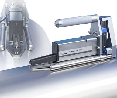
An example of fixturing to hold a profiling drive on a large cylindrical roller.
For these parameters, a skidless probe is required. A skidless probe incorporates a smooth, flat internal surface as the reference so that the probe can respond to waviness as well as roughness. Thus, when a waviness callout is specified for an OD, the alignment of the probe becomes critical. If the axis of the part is not aligned with the reference surface in the skidless probe, then when the probe passes over the crown of the part, it would look like a curved surface compared to the reference of the probe. It would be difficult for the untrained eye to differentiate the curve of the crown from long-wave surface irregularities in the part. Although making this alignment on a bench-mounted surface finish system is straightforward, it is not so with some large shafts with critical finishes.
Let us say we are trying to inspect a large printing roller. One can grasp how short-wave surface finish could be a problem. These short-wave peaks and valleys could cause too much ink to stick to the roller, or maybe not enough. On the other hand, if the short-wave finish is good but there are some long-wave high and low spots — profile issues — then there may not be the correct contact between the rollers or the paper. This is where profiling of the large OD becomes critical. And it is just as critical to make sure that the probe testing the part is perfectly aligned with the part.
Profiling drives tend to be fairly large, especially when they take very long traces. Trying to manually hold and align the system to the part's axis and be stable at the same time is a Herculean effort. This is where simple but effective fixturing can make the user's job a lot easier. Adding an alignment attachment to the surface profiling drive ensures that the probe follows the crown of the part and provides an accurate and repeatable result.


Related Content

3 Considerations for Revising Design for Manufacturing Efforts
When revising part designs, investigate the 3D CAD, the 2D drawing and the part’s functional requirements to determine which details should be tightened up.
Read More
How to Determine the Currently Active Work Offset Number
Determining the currently active work offset number is practical when the program zero point is changing between workpieces in a production run.
Read More
How to Meet Aerospace’s Material Challenges and More at IMTS
Succeeding in aerospace manufacturing requires high-performing processes paired with high-performance machine tools. IMTS can help you find both.
Read More
4 Manufacturing Trends That Cannot Be Ignored
The next five years will present their own unique set of challenges, and shops can alleviate them by embracing these technologies and trends.
Read MoreRead Next

What Do Manufacturers Really Know About the Surfaces of the Parts They Are Producing?
Knowing only the average roughness may not be enough. Other surface parameters can affect product quality.
Read More
OEM Tour Video: Lean Manufacturing for Measurement and Metrology
How can a facility that requires manual work for some long-standing parts be made more efficient? Join us as we look inside The L. S. Starrett Company’s headquarters in Athol, Massachusetts, and see how this long-established OEM is updating its processes.
Read More