
CAD/CAM Considerations For Micromilling
Milling with tools that are smaller than 100 microns in diameter presents equipment design and toolpath-generation challenges. This NC software maker offers strategies for creating safe, optimized tool paths for micromilling.
.jpg;width=70;height=70;mode=crop;format=webp)


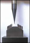
Milling with cutting tools that measure 0.1 mm in diameter, such as the one shown here, creates challenges for both equipment and programming software.
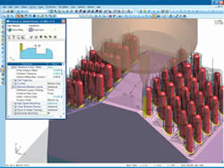
Ridges that remain when milling a tight radius can be cleaned using a zero-overlap trochoidal tool path. In this method, tool back motions are raised from the workpiece in the Z axis and the tool then plunges tangent to the tool path on succeeding forward motions to create a better surface finish.
The challenges involved in designing machine tools, cutting tools and fixtures to effectively mill features on miniature molds and microcomponents are daunting. The same could be said for optimizing tool paths for a tool that a machine operator probably won’t be able to see or hear while it’s in cut. Unlike standard milling operations, there’s no way that a machine operator can tell just how a tool is behaving while cutting in order to make the necessary changes to optimize the process. In addition, the toolpath strategies that might be suitable for “typical” milling work do not always scale down elegantly to work for micromilling applications.
Still, there is an increasing demand for small part machining of medical, electronics and optic components. Recognizing this trend, the Fraunhofer Institute for Production Technology (IPT) in Aachen, Germany, recently sponsored a micromilling research project that brought together machine tool equipment manufacturers and mold makers with the goal of developing effective micromoldmaking strategies and processes. The struggle in creating NC software for micromilling has been effectively calculating tool motions with a tolerance of 0.1 micron. Cimatron (Novi, Michigan) is one software company that took part in the IPT project. The result was upgrading Cimatron E NC software to include a variety of functions for micromilling work.


Uri Shakked, a product manager for Cimatron who specializes in micromilling, offers the following five considerations when generating tool paths for micromilling applications.
1) Develop machining strategies appropriate for micromilling. Similarities between high speed machining (HSM) and micromilling do exist, such as avoiding sharp tool motions. When approaching corners, tool paths should be rounded, and the amount of that roundness depends on the machine tool and the feed rate. When micromilling, rounding becomes virtually useless below a certain value. Rounding of 0.2 mm, for example, is too large because typical micromilling stepovers are extremely small (approximately 0.01 mm). In this example, the roundness value is 20 times that of the stepover value, which means there would be wide gaps between sequential passes, high scallop height and poor surface quality.
The zero-overlap trochoidal method developed by Cimatron offers a way to clean such ridges. This method machines all relevant areas in a trochoidal style, but in order to prevent double-machining, tool back motions are raised from the workpiece surface in the Z axis. The tool then plunges tangent to the tool path on succeeding forward motions (see image on the following page).
HSM uses high cutting feeds to allow the chip to remove the heat that results from cutting; high spindle speeds to generate high cutting feeds; and high feed rates to reduce machining time and allow cutting with small stepover values. The feed rate, though, is limited by the tool’s maximum chip size per cutting edge. Because micromilling cutting tools have such small diameters, the spindle speed is often too slow to produce a high cutting feed, which, in turn, limits the maximum attainable feed rate. For example, to maintain a cutting feed of 100 meters per minute with a 10-mm cutter, the spindle should rotate at approximately 3,200 rpm. For a 0.1-mm cutter, the spindle would have to rotate at 320,000 rpm. Such a high spindle speed currently isn’t available. The maximum cutting feed possible with a 0.1 mm cutter is approximately 15 meters per minute—far from being considered HSM.
2) Conventional milling is generally more effective than climb milling. The decision whether to use conventional or climb milling for micromilling applications depends largely on the part feature being machined. Considering the delicate features typically found on micromolds and microcomponents, conventional milling is generally the milling method of choice.
Conventional milling is best suited for micromilling when the tool is long or the workpiece wall is very thin. As a cutting edge starts a conventional milling cut, the chip size is essentially zero and becomes thicker as the tool rotates. As the cutting edge penetrates the material, the force between them builds and the cutting edge tends to be drawn into the workpiece. This provides for a stable cutting condition that is well-suited for soft materials and delicate features.
However, conventional milling can potentially damage the tool’s cutting edge. As the cutting edge finishes the cut, it pushes away from the material. As it rotates back into a cut, it digs into the material. This causes the force on the cutting edge to rapidly change directions, shortening tool life.
In climb milling, the cutter engages the material at maximum chip size, and the tool and the part tend to push away from each other. The machine tool, workpiece and cutting tool must be robust enough so that vibrations are not introduced. Otherwise, cutting tool life would be shortened and surface quality would be poor.
3) Combined roughing/finishing operations may be necessary. Roughing and finishing passes are traditionally performed as separate operations, using different spindle speeds, feed rates and depth of cut. However, this might not be possible when micromilling, especially when machining tall, thin walls or bosses on miniature parts. The wall thickness after a roughing operation will not provide sufficient support for the finishing operation, causing the walls to vibrate or possibly fracture during finish milling. At the very least, wall surface finish would be unacceptable.
When micromilling, cutting thin walls, roughing and finishing should be combined into a single operation, cutting layer-by-layer down the Z axis on alternating sides of the wall. The cutter should be tilted away from the wall to guarantee a single contact point between the cutter and the wall.
4) Constant tool load should be maintained. In standard moldmaking applications, a machine operator will often manually adjust feed rates, change tools if needed or manually edit the tool path to make it more efficient. Because of the miniature size of the part and tools used in micromilling, an operator has no practical way to see or hear what’s going on during the machining process. That’s why the micromilling software must be able to accurately maintain a constant chip load throughout the cut.
Cimatron software recognizes actual remaining stock and uses that knowledge to make adjustments depending on the tool load throughout the entire process. This quickens machining time while protecting the delicate micromilling tools from breaking. During a roughing operation, in which the workpiece shape is changed dramatically, the software simulates the remaining stock after each layer. This enables the tool to go into locations that were cleaned by previous layers, thus allowing short tools to cut into deep areas.
During a clean-up operation, the system can detect excessive material and automatically apply re-roughing operations. The re-roughing motions prevent tool breakage, maintain constant tool load and deliver higher surface quality. Depending on how much material is removed, the software will automatically make changes to the feed rate or possibly divide the tool path into several down passes.
5) Be mindful of CAD/CAM translation problems. Data translation errors between separate CAD and CAM packages adversely affect machining accuracy, and these inaccuracies are exacerbated when micromilling. Integrated CAD/CAM packages eliminate such data translations. For example, a translation error resulting in a 0.005-mm gap between two surfaces on a relatively large part might not be problematic because the part could be polished. Polishing often isn’t possible on miniature molds or microcomponents, so a gap of the same size on a micromilled part would clearly be visible.
Almost any CAM programming job requires some geometry-mending procedures, which means CAM software should include built-in CAD capabilities. When making a mold, cooling and ejector holes are typically capped to prevent the cutting tool from machining into them. Also, surfaces must be extended to protect areas that will be machined in another setup and a draft angle will be applied. The ability, or inability, to create or modify part geometry impacts the way the tool path is programmed.
This CAD-for-tooling work should be done by a toolmaker who knows the needs of the machining process, such as the NC programmer. In many cases, only during the programming process does it become clear that a certain geometry modification is required.


Related Content

10 Tips for Titanium
Simple process considerations can increase your productivity in milling titanium alloys.
Read More
How to Tackle Tough Angled Pocket Milling With Two Tools
Milling a deep pocket with a tight corner radius comes with unique challenges, but using both a flat bottom drill and a necked-down finishing tool can help.
Read More
New Modular Tool Options for Small Spindle Milling
Tooling options have been limited for small spindle milling applications. Now modular, indexable systems are available that provide broad flexibility to get the right cutter for the job with less inventory and at lower cost.
Read More
A New Milling 101: Milling Forces and Formulas
The forces involved in the milling process can be quantified, thus allowing mathematical tools to predict and control these forces. Formulas for calculating these forces accurately make it possible to optimize the quality of milling operations.
Read MoreRead Next

The Changing Face Of CNC Programming
The Future of Machining - 2005 Efforts to create a CNC-usable product data model are inching forward, but in the meantime, advances in CAM software will make the programmer's job function super-efficient rather than superfluous.
Read More
The Cut Scene: The Finer Details of Large-Format Machining
Small details and features can have an outsized impact on large parts, such as Barbco’s collapsible utility drill head.
Read More
