
Don't Touch That Tool
Tool measurement is critical to the metalcutting process. Exact knowledge of a cutter’s length, diameter, even profile, and the ability to measure and monitor these dimensions over time, can reduce variability and help optimize the process. Here’s a look at how non-contact tool measurement and breakage detection benefit your metalcutting process.

Share


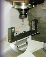
Figure 1 — The first step to bringing the laser system online is to calibrate. This tool has known dimensions and forms the measurement basis for checking cutting tools. This calibration tool can also be used to monitor thermal growth of a machine tool over time.
Figure 2 — Diameter and length measurements can be made on a variety of cutter configurations. Here, two points are measured to determine the length and diameter of this end mill. The cutter is rotating while the measurement cycle is run.
Figure 3 — Ball nose end mill radii can be established and then checked for wear using the laser scanner. Two dimensions, an inner and outer shown in red, establish the optimum contour on the outside and the minimum deviation on the inside. The difference is the programmed tolerance.
The cutting tool represents the end effect of a long chain of process parameters. The CAD file represents the design of the workpiece. The CAM file prescribes tool path. All the accuracy and speed designed and built into the machine tool, as well as the stability of the workholding system, must come together to make the first chip.
But none of the preceding will produce satisfactory results if the actual cutting tool is longer, shorter or a different diameter than programmed. Moreover, dimensions that were "dead-on" using a static measurement gage can be affected by dynamics created when the cutter goes in motion.


An answer seems to be to measure the cutter as it rotates in the spindle, within the cutting zone, as often as wear characteristics warrant. A system manufactured by Blum LMT, Inc. (Fort Mitchell, Kentucky) accomplishes this using a laser to measure cutter length, diameter and flank wear and to detect missing or broken tools.
Laser Is Key
Lasers offer two distinct advantages for tool measurement. The beam is basically a "one size fits all" gage, and it’s a non-contact system of measurement that is virtually impervious to contamination.
The hardware for Blum’s laser measurement system is relatively simple and unobtrusive. Designed to operate in the harsh environment of a machine tool’s cutting zone, the U-shaped scanner that holds the laser unit is the only visible component.
When the laser beam is actuated, it passes from one side of the "U" to a pick-up on the other leg. Since it is designed to operate inside the work area of a metalcutting machine tool, a pneumatically actuated shutter and blow-off protect the optics from contamination.
In operation, the laser acts like a high precision photoelectric beam that is activated when broken. It’s essentially a high precision version of the photoelectric beam used on garage doors. When the beam is broken, the door stops or reverses.
Likewise, when a cutter interrupts the scanner beam, an output signal is sent to the machine’s CNC or PLC. Resident software compares the coordinates of the point of beam contact with known values in the control’s tool data tables. Activation occurs when the cutter shades 70 percent of the laser beam.
The scanner can be mounted directly in the cutting zone, on the worktable or elsewhere. Orientation is not a problem, and where space is limited the scanner can be mounted vertically or at an angle.
A diode laser generates the beam used to measure cutting tools. The laser beam is a visible red light with a wavelength of 670 nanometers. Power output is less than one Watt. As a class 2 laser, its power is less than that of a laser pointer. It does not require a warning label or operator eye protection.
The scanning unit is connected by umbilical to the machine tool CNC, or it can operate off a PLC. Successful interfaces for most popular CNC units have been developed. Programming macros have been developed by Blum to run most tool checking routines with a G or M code command.
Why In-Process, Dynamic?
Most tool setting is done off-line in a tool setting gage. Dimensions are verified and tagged correct. The cutter is loaded in the machine, and its dimensional data is read into the control by a bar code or entered manually.
The first cutter is brought into proximity of the workpiece, and a gage block establishes the workpiece tool offset. This system works well but is built on a series of static measurements.
What isn’t known in traditional tool setting is how the toolholder, drawbar and spindle are all going to align from tool to tool. Perfect repeatability between a cutting tool and spindle is rarely achievable.
That’s why in process, dynamic measurement of each tool as it rotates in the spindle, within the workzone, is gaining acceptance in many shops. An example of this is General Tool Company (Cincinnati, Ohio). It is a premier job shop serving aerospace, and power generation industries, and a builder of special machines.
Like many shops across the country, General Tool feels the shortage of skilled metalworking personnel. It is looking to get more work through the shop with its existing workforce.
General Tool sees a tool monitoring and measurement system like Blum’s as helpful to its drive to better productivity using more untended and lightly tended operations. "In setup reduction, for example," says company industrial engineer Greg Kramer, "this laser system is faster at getting the cutter engaged in a job than traditional gage blocks and touch-off cycles."
The company has the laser system on its newest five-axis machining center, a Deckel Maho 200P. It’s a big, versatile machine tool with a standard #50 taper, 8,000 rpm spindle that can also run a motorized 42,000 rpm HSK 32 spindle that’s automatically exchangeable.
"We see this machine doing a variety of workpieces using both high speed and conventional machining techniques," says Mr. Kramer. "Some of our more challenging and dimensionally critical jobs will go across the machine. With traditional static tool setting, there is quite a bit of handling of the cutters. The laser scanner helps us get more consistent readings from operator to operator because it’s automatic."
Highly accurate, repeatable measuring is vital for the precision jobs that General Tool tackles. But what can a laser tool measurement gage actually do for the shop?
What Can It Do?
Use of the laser as a measuring device provides a flexible tool for determining cutter dimensions. It can measure concentric tools, such as drills, or non-concentric tools, such as end mills and face mills. It can measure single cutting edge radii as found on ball nose end mills and periodically re-check them for wear.
The laser scanner can accommodate very small diameters. Cutters with a diameter down to 0.012 inch (0.3 mm) can be measured with accuracy within a few microns.
Larger tools too can be accurately measured without any changeover of hardware or software. Basically one scanner fits all cutters.
Before the laser can be used to measure, it must be calibrated. This process is necessary to determine the precise trigger point position for the laser light beam and must be established for each axis.
Calibrating the laser scanner is a relatively simple procedure. A cylindrical reference-pin with two known diameters and a known radius is used for the procedure (Figure 1, right). The known dimensions of length, height and radius are entered into the calibration table in the machine control.
Passing the spindle-mounted reference-pin through the beam establishes the measurements in space. Deviations from the known measurement are established as axis offsets. With these values in the tool table, any cutter can be accurately measured.
For example, center-cutting tools such as drills are quickly measured for length with two passes through the beam in the Z axis. First, at rapid traverse with the spindle at operational rotation, the drill breaks the beam.
This triggers an axis retract which is followed by a second Z-axis fine feed to a point where the cutter tip breaks the beam. This establishes the actual length of the cutter in the spindle. It all takes a few seconds.
The measurement result is written under the tool number into the tool-offset table in the CNC. The measurement routine is an automatic macro built into the measurement software.
Cutting tools such as end mills, face mills, milling cutters and others, with unknown length and diameters, can be measured at spindle speed using the laser scanning gage (Figure 2, left). Tool length is measured first by moving the cutter periphery into the laser beam with a Z-axis move. Next, the diameter is calculated by moving one side of the cutter through the beam.
Because the tool is rotating and the laser is triggered by the first cutting edge that breaks the beam, any misalignment of inserts or high edges can be identified. With this data, routines in the software can calculate spindle runout where each cutting edge is monitored for being within a programmed runout tolerance. Measuring accuracy of ±1 micron can be achieved using these routines and is accomplished within a few seconds.
When measuring cutter diameter, the laser scanner simply detects the first edge to break the beam. With the cutter rotating, this is the maximum or longest cutting edge.
In order to monitor radial runout, which can be caused by errors in tool clamping and flight circle deviations, or to monitor the radial tolerance between the maximum and minimum cutting edges, the cutter runs into the beam to a depth equal to the tolerance. Once in the beam, the cutter is moved through the beam taking what is in effect a scanning stroke. If the beam remains broken during this routine, the tool is in radial runout tolerance.
Cutters with rounded edges or forms such as ball nose end mills or taper tools can be measured with a laser scanner (Figure 3, right). This is accomplished by establishing the largest permissible outside cutter edge, the cutting edge outline and the starting and aiming point of the contour. These are established using parameters in the measurement software.
Tool breakage is an important asset of a tool measurement and monitoring system. The fine measurement resolution of the laser makes it possible to determine the condition of individual cutting edges. Wear, chipping or fracture of each cutting tooth can be determined quickly and checked as often as necessary.
Check Machine Tools, Too
All machine tools have temperature drift to some extent. Part of the machine tool designer’s job is to understand and anticipate this fact when putting together the components, which comprise the machine.
In most machining operations, the dimensional effects of thermal growth are gradual and, over time, predictable. The laser system for measuring tools can be used as a thermal sensing gage for the machine tool.
To accomplish this, a shop uses the laser calibration tool to check each machine axis for growth. The tool has known dimensions in X, Y and Z axes. Comparing laser measurements taken over time can help a shop detect axis drift and compensate for it.
It For You?
For applications where dynamic, in-process monitoring of the cutter is a benefit—high speed applications, unattended or lightly tended operations are examples—a non-contact laser measurement unit can help productivity and quality. Delicate tool coatings that could be influenced by contact gauging and processes where consistency of measurement among individuals are a few of the variables that can be addressed using a laser measurement system such as Blum’s.


Related Content

Finding the Right Tools for a Turning Shop
Xcelicut is a startup shop that has grown thanks to the right machines, cutting tools, grants and other resources.
Read More
Orthopedic Event Discusses Manufacturing Strategies
At the seminar, representatives from multiple companies discussed strategies for making orthopedic devices accurately and efficiently.
Read More
Inside the Process of Cutting Tool Recycling
Global Tungsten & Powders, part of the Ceratizit Group, sheds light on the processing steps that convert a shop’s used inserts into new tools and other applications.
Read More
Briquetting Manufacturer Tools Up for Faster Turnaround Times
To cut out laborious manual processes like hand-grinding, this briquette manufacturer revamped its machining and cutting tool arsenal for faster production.
Read More