
Drilling Deep Holes On A VMC
The recipe for best results is simple: Start with a rigid machine, add a high pressure through-the-spindle coolant system, then combine these with the right drill geometry plus the right speeds and feeds.


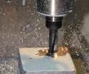
When coolant cannot reach the bottom of a deep hole, chips are likely to clog the flutes allowing heat to build up and damage the drill and the workpiece.

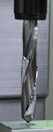
Drill geometry must be matched to the operation and workpiece material for efficient deep hole drilling. The wide flutes on this drill allow better chip evacuation.
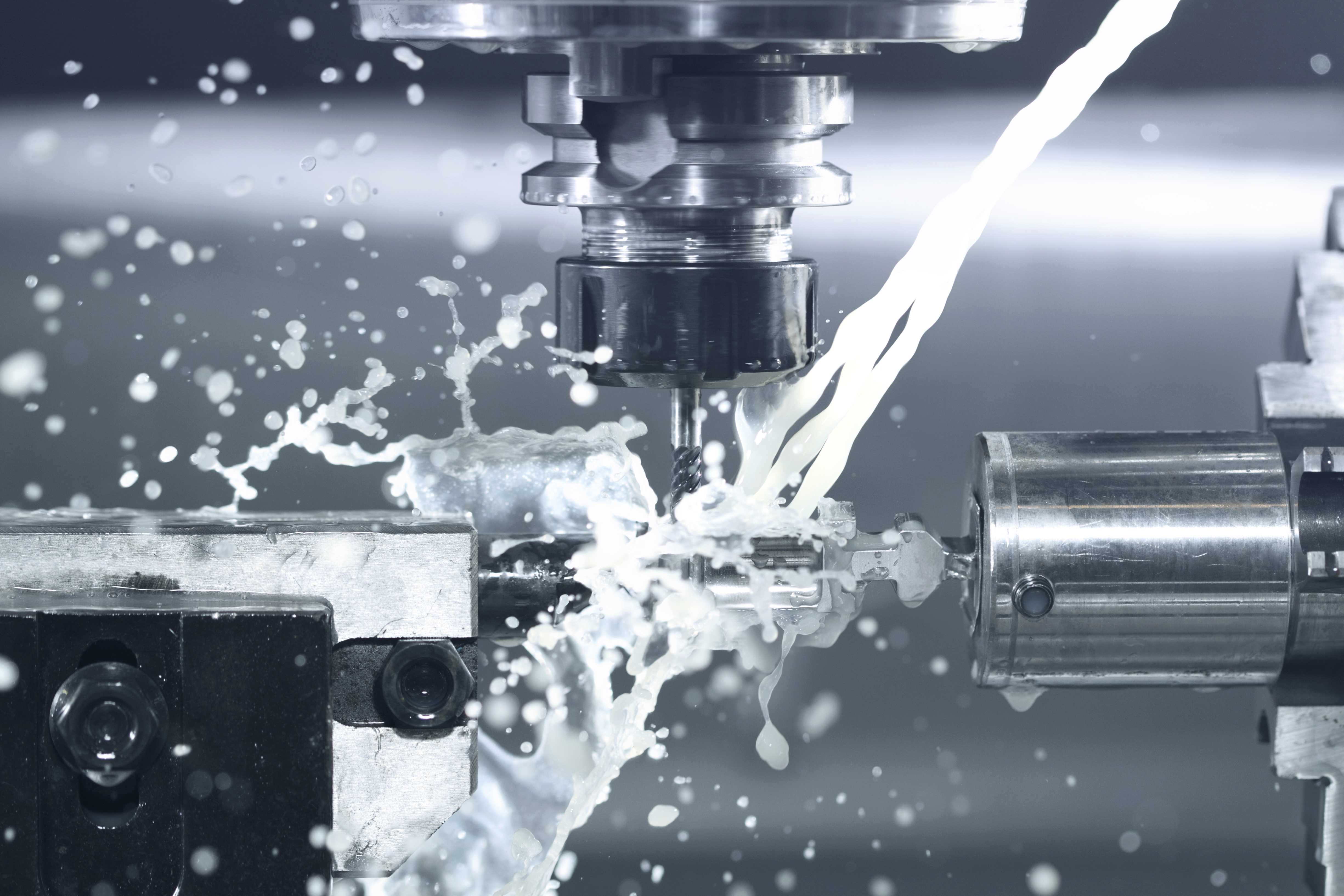
High pressure coolant through the spindle is used when drilling deep holes to flush chips up and out of the hole. This technique eliminates pecking cycles, reduces potential damage and tool wear and increases productivity.
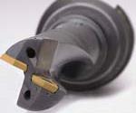
This inserted tool features holes through its center, enabling high-pressure coolant to reach the bottom of a hole, where the coolant flushes chips and carries away heat.
Hole drilling is the most common operation performed on a vertical machining center. When this operation involves drilling deep holes, it becomes one of the most challenging. However, there are very effective ways to meet this challenge.
The goal is to produce these holes accurately, repeatably and with superior surface finish—and to do so economically.


The most important ingredient in successful deep-hole drilling is understanding. You have to understand what happens inside the hole as it is being drilled and how this knowledge guides your choice of the most effective techniques.
The Dynamics Of Deep-Hole Drilling
Strategies for deep-hole drilling address three primary issues: evacuating chips without damaging the surface finish, delivering coolant to keep the drill and workpiece material cool, and minimizing cycle time. Other important factors include accuracy, repeatability and surface finish.
Typically, a deep hole is defined by the ratio of the diameter to depth. Usually a ratio of 5:1 or greater is considered deep-hole drilling. For example, a 5-inch deep by 1-inch diameter hole is considered deep, as is a 0.125-inch diameter hole that is 1 inch deep.
Chips must be small enough to move up the tool’s flutes and out of the way. Long, stringy chips can damage surface finish and cause premature tool wear or breakage. Coolant has to get to the tool tip to keep the tool and workpiece cool, as well as force chips out of the hole. A rigid machine tool with good damping characteristics and low spindle runout is required to hit targets for accuracy, repeatability and surface finish. Of course, the right drill geometry will make deep-hole drilling operations much more efficient.
Controlling Chip Size And Shape
Some materials form very small chips that flow out through the flutes easily. Other materials form chips that are long and stringy. One approach to controlling chip size and shape is the use of special machining cycles. Deep-hole cycles and peck drilling cycles are used to break chips so that they are small enough to flow up through the flutes on the tool without causing damage to the surface or promoting premature tool wear.
Generally, there are two types of deep-hole cycles. One uses equal pecking depths to reach the final depth. The other uses variable pecking depths, wherein each peck is followed by pecks of successively shorter increments.
Most machine tool controls offer deep-hole drilling cycles, which feed the drill into the material a specified distance, pull the tool all the way out of the hole and then feed it back into the hole. With this kind of deep-hole cycle, chips may fall into the hole when the drill pulls out and flood coolant washes in. This condition is especially likely to occur when cutting steel. When the tool feeds in again, it will hit any chips at the bottom of the hole. Chips encountered by the tool start spinning, forcing the pressure of the tool to cut or melt its way through the chip. On a manual mill, the operator would feel the chip spinning and would stop drilling to blow out the hole and clear stray chips. However, these drill cycles can be programmed to stop just above the last peck to avoid this situation.
An example of a variable peck cycle is one starting with a 1.00-inch peck. The next peck would only go 0.50 inch deeper, followed by one 0.25 inch deeper, with the last peck going only 0.05 inch deeper than the previous peck. As the drill goes deeper into the hole, the decreasing peck depths help eliminate chip impaction around the tool. The deeper in the hole that the drill gets, the more difficult it is for coolant to get to it, so pecks are used both to evacuate chips and get more coolant to the tool tip.
The ability to write special cycles with the machine tool control enables routines to be captured and, as with a fixed cycle, executed automatically whenever a new position is written into the program. (Such a subroutine feature is found on the Fadal control unit, for example.)
Peck drilling, although not solely a deep hole cycle, is used to break chips by withdrawing the tool only a small distance after each peck, eliminating the problem of chips falling back into the hole. The length of the peck determines the chip length, eliminating chips that wind around the tool and are commonly called angel hair. These chips cause coolant to dribble down the hole only to be thrown off and out by the drill, thus allowing heat to build up in the drill and cause excessive tool wear. Ultimately, this condition can lead to catastrophic tool failure. The disadvantage of deep-hole and peck cycles is that they take longer to finish each hole. It takes time for the tool to feed down, rapid out of the hole, rapid back and feed down again. Multiply the time for a peck cycle by the number of holes to be drilled, and the delay adds up. Even if total time per hole is increased by just seconds, hole drilling efficiency is diminished. On long production runs, these inefficiencies can be a serious issue.
Getting Coolant To The Bottom Of The Hole
Strategies for avoiding problems during deep-hole drilling operations include different types of coolant delivery. Three types of coolant systems are common to VMCs: flood coolant, low-pressure through-spindle coolant and high-pressure through-spindle coolant. With flood coolant, less and less coolant reaches the tool tip the deeper the drill penetrates the workpiece. Eventually, no coolant can get to the bottom, and machining occurs dry. As a result, chips become impacted in the flutes of the tool even though coolant is visibly flowing over the top of the hole. In fact, the hole ends up being dry cut, while the tool heats up and is subjected to premature wear or breakage.
Heat from the drill may also work harden or “heat treat” the workpiece in the vicinity of the hole. Friction from the drill heats the workpiece, and when coolant finally reaches the heated material, the coolant quenches it. On the subsequent peck, the drill encounters the hardened material, causing excessive tool wear or a broken tool and damaged part.
The essence of successful deep-hole drilling requires a method of getting coolant down to the tip of the drill where it can remove heat and evacuate chips. Coolant-through-spindle systems provide the best solution. Several builders of VMCs offer this feature as an option. For example, Fadal offers a 350-psi Coolant-Thru Spindle system that delivers coolant through the tool tip. Such features are fairly inexpensive methods for getting coolant to the bottom of the hole. Systems that deliver coolant at high pressure, such as the Chip Blaster, which boosts coolant pressure to 1,000 psi, provide even better chip evacuation.
With low-pressure coolant-through-spindle systems, the programmer can safely increase the depth of pecks and in some cases completely eliminate pecking cycles altogether, saving production time. With high-pressure coolant-through-spindle systems, not only is pecking eliminated or reduced, but higher feed rates and spindle speeds also can be used. As a bonus, this system extends the life of the tool. High-pressure coolant-through-spindle systems provide the best scenario for decreasing cycle time and increasing tool life.
The high pressure of the coolant breaks up chips and forces them up the flutes and out of the hole. Cycle times go down, because the pecking process is eliminated while spindle speeds and feed rates can be increased. With higher feed rates, chips tend to form better.
Delivering coolant through the spindle also improves the production of through-holes. When coolant cannot reach the tip of the tool adequately, and as the drill approaches the breakthrough point, material at the edge of the hole becomes thin and hot before being pushed away from the tool. With coolant delivered at the tool tip, heat is less likely to build up in the material as it thins, allowing it to be cut and not pushed away. A clean edge forms around the bottom of the hole. This condition makes the hole easier to deburr.
Drill Geometry
Drill geometry is a key factor in successful deep-hole drilling. Flute size and spacing affects chip evacuation, for example. Drills with open flutes enable chips to flow up and out of the hole more easily, especially with coolant-through-spindle systems. But without good coolant flow at the bottom of a hole, even open flute designs are subject to chip clogging and drill breakage.
Today’s technology enables toolmakers to design tools for drilling with features that better facilitate chip evacuation and minimize overheating. Made of higher-grade carbide steel for longer life, these tools feature new shapes, which assist deep-hole drilling operations. Because the tools are stiffer, they are less likely to wander in deep-hole drilling operations.
Some carbide tools are now available with coolant holes through their length for high speed machining. Although these tools get more coolant to the tip, they can be very expensive. Some of these new tools require high coolant pressure, high spindle speed and high horsepower to be effective. If the machine tool lacks these features, then investing in these tools is wasteful.
Standard tools for drilling feature a wide web at the tip. Some drill designs modify this web by splitting it and making it thinner. Further changes in the geometry of the tip may also occur. These special drill geometries, such as those produced on Winslow drill sharpening machines, improve deep-hole drilling. These drill points allow deeper holes to be made, plus they improve finish, straightness, accuracy, tool life and production rates.
Also, special coatings are sometimes utilized on the edge of the tool to minimize frictional heating. Coatings help form better chips and get them up and out of the hole more quickly. The increased cost of these coatings is justified by extended tool life.
Machine Tool Features
Machine tool rigidity has a major impact on deep-hole drilling because the less stable the foundation of the machine, the more vibration the head and table will generate, causing the tool to break down. For deep-hole drilling, features to look for include castings with uniformly thick walls to avoid heat distortion, box ways with a large surface contact area, a very strong head and a column that does not flex. A low-vibration spindle is also required.
Lack of stiffness in the machine tool causes the column to bend when pressure is put on the head from deep-hole drilling operations. As a result, the drill may bend, decreasing accuracy and causing tool wear, eventually leading to a broken tool. With excessive pressure on the head, the drill enters at an angle and will miss the correct position.
Other features are also helpful. For example, a system for maintaining spindle speed as the load increases assures a constant chip load on the drill. If the spindle speed decreases during a cut due to tool load, the chip load will increase and risk breaking the tool. The spindle vector drive system on Fadal VMCs provides this function. Another feature found on these VMCs is dual spindle motor windings, providing low range speeds as high as 2,500 rpm and high range speeds of 2,500 to 10,000 rpm. This feature expands the capabilities of the vector drive spindle motor by doubling horsepower at high spindle speeds. Also useful in deep-hole drilling is Tool Load Compensation, enabling the programmer to designate a tool load that dynamically regulates the feed rate as cutting conditions vary.
Meeting Objectives
Coolant through the spindle, drill tip geometry, carbide tooling, coatings and cycle selection are important factors when drilling deep holes. Each of these factors affects hole finish, integrity, production time, tool life and the burr at the bottom of the hole. The best scenario in deep-hole drilling is to use high-pressure coolant, a tool with open flutes, carbide tools with a coating and a single peck to create the hole.
While most of us have to make do with the tools at hand, a wide choice of drills, features and machine tools is available. For any given job, there are multiple strategies, so knowing how different materials, drills, features and machine tools react in different situations will determine how well machining objectives can be achieved.
About the author: Daniel de Caussin has been with Fadal Machining Centers (Chatsworth, California) for 25 years, directing the applications, documentation, and training departments.


Related Content

10 Ways Additive Manufacturing and Machining Go Together and Affect One Another
Forget “additive versus subtractive.” Machining and metal additive manufacturing are interconnected, and enhance the possibilities for one another. Here is a look at just some of the ways additive and machining interrelate right now.
Read More
Additive/Subtractive Hybrid CNC Machine Tools Continue to Make Gains (Includes Video)
The hybrid machine tool is an idea that continues to advance. Two important developments of recent years expand the possibilities for this platform.
Read More
Twin Spindle Design Doubles Production of Small Parts
After experiencing process stalls in the finishing stage of production, Bryan Machine Service designed an air-powered twin spindle and indexable rotating base to effectively double its production of small parts.
Read More
In Moldmaking, Mantle Process Addresses Lead Time and Talent Pool
A new process delivered through what looks like a standard machining center promises to streamline machining of injection mold cores and cavities and even answer the declining availability of toolmakers.
Read MoreRead Next

Obscure CNC Features That Can Help (or Hurt) You
You cannot begin to take advantage of an available feature if you do not know it exists. Conversely, you will not know how to avoid CNC features that may be detrimental to your process.
Read More
3 Mistakes That Cause CNC Programs to Fail
Despite enhancements to manufacturing technology, there are still issues today that can cause programs to fail. These failures can cause lost time, scrapped parts, damaged machines and even injured operators.
Read More
The Cut Scene: The Finer Details of Large-Format Machining
Small details and features can have an outsized impact on large parts, such as Barbco’s collapsible utility drill head.
Read More