
Follow Your Blisk
Here are some considerations for successful blisk machining.
Share


Phillips Corporation
Featured Content
View More
Phillips Corporation - Education
Featured Content
View More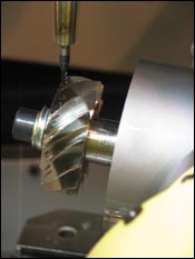
The potential for long tool assemblies combined with the need to approach the blisk from multiple directions can call for a machine that has tight repeatability over a large volume.
There was a time when machining blisks of the sort used in aircraft engines was dominated by a small number of expert companies using heavily customized software systems. More recently, however, reductions in the cost of five-axis hardware and an increase in the power of programming software have expanded the number of shops that can machine blisks effectively. For that expanded number of potential suppliers, this article describes some of the factors involved in successful blisk machining.
Blisk Basics
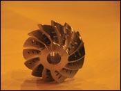
A “blisk” is a disk with a series of blades (or airfoils) attached. The word is a contraction of “blades on a disk.” Some blisks are machined from solid billet using multi-axis CNC machines. An alternative method is to weld the blades and disk together. Even in the latter case, though, there is a need for multi-axis machining to remove the flash left by the welding.


The most fundamental factor to consider in a blisk machining process is the range of variation in blisk design. With improvements in FEA software packages, engineers have designed more complex airfoil forms. Increased twist-to-camber ratio, reduced cross-sectional wall thickness and elaborate leading edge profiles can all increase the thrust potential of the blade to improve the efficiency of the engine. However, all of these changes also add to the machining challenges.
The design even varies among related blisks. In aircraft engines, the blade complexity tends to ease toward the rear of the engine. Blisks toward the front have larger blades with a high degree of twist, and these are more difficult to machine. With simple blisks, it is generally possible to machine the component from various angles, giving the programmer a number of options. When working on more complex blisks, however, the programmer is often challenged to find angles and tool assemblies that can machine the shape efficiently, or even at all. In fact, the machine tool itself needs to be chosen with this complexity in mind.
The Machine Tool
When considering the machine tool to use in blisk machining, blisk size is dramatically important because much more space will be needed just to let the tool assembly navigate around the part.
For example, in the illustration on the following page, a blisk is positioned on a rotary axis on the table of a CNC machine. A second rotary axis is located on the head of the machine. The complexity of the blisk design requires the cutting tool to approach the blisk from two sides. In addition, the shape of the blades, the size of the gap between the blades and the size of the smallest features on the blade all create the need for a relatively long tool assembly. In this not-uncommon set of situations, if the tool assembly’s range of motion is drawn as a working envelope around the blisk, it becomes clear that the actual stroke of the machine must be significantly larger than the blisk itself. Because of the potential for circumstances such as these, even a relatively small blisk can require a machine with tight repeatability over a large volume.
Emphasis also has to be placed on generating tool paths that make efficient use of the capabilities of such a machine. In five-axis machining, the programmer has to avoid tool paths containing excessive axis reversals or erratic motion. Axis reversals happen when one or more rotary axes on the machine are forced to change direction in a very short time frame. The cutting force drops as the rotary axis slows down, reverses and accelerates. This pause tends to leave a witness mark on the part. The reversals also place extra strain on machine components. An advanced milling software package (Delcam’s PowerMill is an example) can help the programmer create tool paths that move the tool across the workpiece with smooth motion at a constant feed rate, avoiding these reversals.
The Control
The complexity of the shapes being machined also places extreme demands on the CNC. In fact, it’s easy to focus on the capabilities of the machine itself and overlook the capabilities of the control.
In an attempt to test the variation between different controls, Delcam recently machined a reasonably complex blisk on different machines in its own in-house tool room. A five-axis finishing tool path was created using a tolerance of 0.01 mm and regular point spacing of 0.1 mm. The tool path was run on all of the machines at a programmed feed rate of 2,500 mm/min in a high-grade titanium. The variation in cycle times can be seen here:
CNC Cycle Time
A 23 minutes
B 12 minutes, 45 seconds
C 8 minutes, 24 seconds
When the test program was run on control A the motion of the machine was jerky, with the feed rate rarely exceeding 800 mm/min. Control B achieved a typical feed rate of around 1,200 mm/min with a smoother motion. Control C regularly exceeded 2,200 mm/min feed rate and had an almost perfectly smooth motion.
What caused this variation? A modern control provides various features that can affect the behavior of the CNC machine. Features such as block-processing time, acceleration/deceleration rates and jerk factors can all be tweaked to adjust the way the control processes the program coming from the CAM system. Control manufacturers also provide advanced features that can be adjusted to refine the performance characteristics of the machine even further.
In our test, control A’s jerk factor was found to be set at a rate that caused the machine to react too aggressively to minute deviations in the five-axis tool path. The aggressive reactions caused a reduction in surface finish quality and a drastic increase in cycle time. Controls B and C were configured similarly to each other, but the advanced settings on control C configured it to more efficiently handle the toolpath data. Analysis of all three controls allowed Delcam to adjust key settings of each machine, so that all three showed considerable improvement in cycle time and surface finish when the machining trials were repeated.
Machining Strategy
Many different machining strategies can be adopted when machining a blisk. The choice is influenced by the shape, size and complexity of the component as well as the material being machined and the way the component is fixtured. In order to determine the best method of machining, the programmer should ask questions such as the following:
- Does the geometry of the component lend itself better to plunge or conventional machining?
- Can the blisk be machined using a single angle of approach?
- If not, what is the minimum combination of angles required?
- Does the blisk need to be finish machined in-line with the airflow across the blisk?
Yet another important consideration is to minimize part vibration. Blisks situated toward the rear of the engine typically have small blades with relatively high cross-sectional wall thickness. These blades can often be machined using a fairly conventional approach consisting of roughing, semi-finishing and finishing. However, when programming blisks near the front of the engine, this process becomes less stable. The combination of increased blade size and reduced wall thickness results in blades that are more susceptible to vibration. The programmer may have to generate programs that leave these blades self-supporting for as long as possible.
A common trick here is to rough a relatively small portion of the blisk and then immediately semi-finish and finish the same area. In this way the programmer leaves the remainder of the blade un-machined, so the part supports itself. This process is repeated down the length of the blade until the part is fully machined.
Workpiece Rigidity (And A Simple Way To Increase
Tool Life)
The CAM programmer’s effort to avoid part vibration may be in vain unless there is also high-quality fixturing. The best possible fixturing solution should be adopted to hold the component rigidly during machining. This will not only increase part quality and consistency, but also prolong tool life.
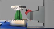
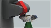
Some novel tricks have been shown to reduce part vibration. During one experiment at Delcam, a simple airfoil was machined within a crude fixture. The design of the fixture consisted of a series of hardened steel “pads” that had been machined to mimic the shape of the airfoil in localized clamping zones. A blade was loaded into the fixture and the hardened steel pads were used to lock the component in place. The main airfoil form was then machined using a simple five-axis finishing strategy. The resulting surface finish was inspected, as was the condition of the cutting tool. This process was repeated, with each repetition followed by an inspection of the finish and tool condition. Eventually there was a noticeable decline in finish quality. Typically this coincided with a loss in the integrity of the tool’s cutting edge. The results of this test gave a good indication of the likely tool life for this particular fixture/workpiece/tooling combination.
Next, the test was repeated, but this time a rubberized foam pad was inserted into the void between clamp and workpiece. The rubberized pad was compressed as the fixture was tightened to the same torque settings as the previous test. Again, a five-axis tool path was run, and the part and tooling were checked after each iteration.
The results of this test were impressive to say the least. The introduction of the pad effectively damped out nearly all vibration in the workpiece. This had numerous beneficial effects. For one, the lack of part vibration permitted a noticeable increase in surface finish from the very beginning. However, the more surprising benefit related to tool life. With the smoother cutting resulting from reduced part vibration, Delcam’s analysis showed that tool life reliably increased by at least a factor of 12.
About the author: Brett Hopkins, machining technology specialist for Delcam North America, is based in North Carolina.


Related Content

The Smarter Way to Take Full Control of Your CNC Machine Shop
Designed to bridge the gap between CAM programmers and shop floor operators, SolidShop provides a seamless, real-time solution for managing G-code, tracking production and eliminating costly mistakes.
Read More
4 Commonly Misapplied CNC Features
Misapplication of these important CNC features will result in wasted time, wasted or duplicated effort and/or wasted material.
Read More
Building a Foundation for AI Success on the Shop Floor
Strong ERP infrastructure and proper planning enable shops to harness the power of AI.
Read More
Legacy After Loss: Writing the Next Chapter of a Family-Owned Machine Shop
When a beloved machinist’s passing left his shop in his children’s hands, the three siblings stepped up, transforming the business to honor his legacy and build a new future.
Read MoreRead Next

WEBINAR: From Machine Data to Guided Action: How Modern Shops Are Closing the Execution Gap
In this webinar, MachineMetrics Product Manager Josh Fish is joined by Pindel Global Precision's Thomas Deslongchamps, for a candid look at what closing the execution gap actually looks like inside a precision machining shop.
Read More