
Hobbing Bevel Gears on a Turn-Mill Center
After deciding to manufacture bevel gears for its own purposes in-house, Index developed a “gear hobbing package” that transforms its R200 and R300 turn-mill centers into gear cutting machines.
When machining typical bevel gears with module 1.15 mm and approximately 25 teeth for its toolholders completely from barstock, Index says that a cycle time of less than three minutes has been achieved.
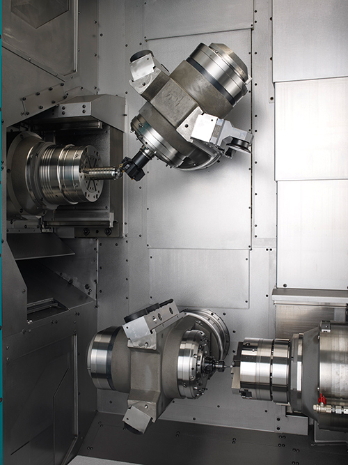
The ability of the turn-mills to accomplish complete gear machining on the front and rear ends simultaneously results in shorter total cycle times and a lower cost per piece.
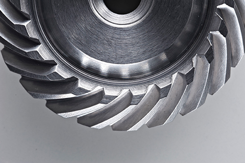
The soft machining process is completely autonomous, with a reliable gear quality of IT5 (A5 in ANSI/AGMA 2015-1-A01, Q12 in AGMA 2000-A88).
Share


Flexibility is an attribute any job shop seeks when investing in a machine tool. One OEM has developed technology that allows bevel gears to be hobbed on two of its turn-mill centers, eliminating setups on other machines, increasing throughput and reducing work cycle times.
After deciding to manufacture bevel gears for its own purposes in-house, Index developed a “gear hobbing package” that transforms its R200 and R300 turn-mill centers into gear cutting machines. This technology is now being made available as an option for new machines and also as a retrofit for those who have already invested in the R series. The package will be offered on additional machines in the coming months.


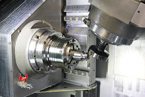
According to Dr.-Ing. Volker Sellmeier, head of technology development at Index-Werke GmbH & Co. KG Hahn & Tessky in Esslingen, Germany, the gear hobbing technology package consists of four elements. The first, of course, involves the R series machines themselves, which feature two motorized milling spindles that perform machining functions in two independent subsystems, including five-axis machining. Both roughing and detail operations can be performed simultaneously on the machines, which have been designed to deliver optimal stiffness, thermal and dynamic stability, and vibration-damping characteristics.
The second element involves the four cutter heads specially developed by Index for this operation. These four heads are required to machine bevel gear sets consisting of a pinion and a wheel. The third component of the package is the OEM‘s bevel gear control cycle that allows users to operate the R200 and R300 machines exactly as they would a conventional bevel gear cutting machine. Its primary function is to translate the values entered into the machine—distance, eccentricity, aid angle, etc.—into the correct relative motions between the tool and the workpiece so that the process matches the approach to cutting a bevel gear on a conventional machine. Finally, Index provides training and insights based on its experience with manufacturing bevel gearing via the continuous indexing Cyclo-Palloid method developed by Klingelnberg, which results in an exceptionally tight contact pattern since the tooth surfaces are fundamentally conjugate—two gears with matching yet inverse features, in other words.
The use of two separate cutter heads results in a tradeoff of sorts. On one hand, two passes are required to machine the convex and concave flanks. On the other, more inserts can be mounted on the cutter head than when taking the conventional approach, which involves an interlocked cutter head. As an example, even with the smallest tool radius of 25 mm, as many as six inserts can be mounted on the cutter head developed by Index, while no more than two will fit on an interlocked version. TiN-coated carbide inserts allow for extremely high cutting speeds. So a certain amount of performance is lost making the two rolling motions while machining the flanks, but using more inserts and higher spindle speeds overcompensates for the lost time, Dr.-Ing. Sellmeier says.
Related Content
-
Orthopedic Event Discusses Manufacturing Strategies
At the seminar, representatives from multiple companies discussed strategies for making orthopedic devices accurately and efficiently.
-
How to Successfully Adopt Five-Axis Machining
While there are many changes to adopt when moving to five-axis, they all compliment the overall goal of better parts through less operations.
-
Shoulder Milling Cuts Racing Part's Cycle Time By Over 50%
Pairing a shoulder mill with a five-axis machine has cut costs and cycle times for one of TTI Machine’s parts, enabling it to support a niche racing community.


