
Smart, Fast Prototyping Informs Redesign for AM
Rapid intelligent prototyping can reveal how best to proceed when developing design guidelines for additive manufacturing.


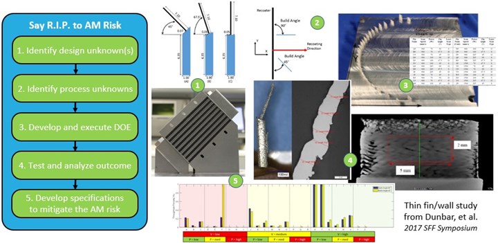
Illustration of steps undertaken by Dunbar, et al., to develop design guidance for thin fins used in AM heat exchangers. Photo Credit: Dunbar, et al.
Rapid prototyping has been the predominant use case for 3D printing and additive manufacturing for over 30 years. With metal AM, being smart and fast is even more important when it comes to prototyping, given the cost of materials, machines and post-processing. Consequently, I introduced the notion of Rapid Intelligent Prototyping (R.I.P.). In this column, I intend to dive deeper and share an example that may spark an idea or trigger a new way of thinking for users developing AM parts for production.
Consider a heat exchanger — a very “hot” application for AM right now (sorry, couldn’t resist the pun). Typically these are made by stacking layers of perforated or finned sheets on top of one another and then welding or brazing them together into an assembly. It is easy to make the sheets, it is easy to make the fins or perforations in the sheets and it is easy to stack them together into an assembly. The end result, though, is often a large, boxy structure that must be “designed around” if you want to incorporate it into a larger system. Look no further that the radiator in front of your car’s engine to see what I mean.


With AM, we can now reimagine what a heat exchanger looks like. For instance, it can be designed to conform to (that is, wrap around) the shape of the system or component that is being cooled (for example, a hot cylindrical pipe). An aircraft engine oil cooler, for example, no longer needs to look like a metal shoebox; instead, the surface area can be redistributed and made to fit within the natural spaces and gaps within an aircraft engine if you employ AM.
In redesigning such a heat exchanger, users may start wondering: How small can I make a wall or fin and still print it? In what orientation should they be arranged? What cross-section should the fins have? Can I vary the fin cross-sections, and if so, what is the best configuration for each fin and the fins as a whole? What is the impact of surface roughness on the fins? What if the fins are not fully dense; would a porous fin create more surface area and be more efficient?
These are but a few of the questions one encounters when (re)designing heat exchangers for AM. While they may appear straightforward and easy to answer, they are not, particularly when it comes to metal laser powder bed fusion (L-PBF). The interactions between the material feedstock being used, the processing conditions in the machine and the design geometry and print orientation are so tightly coupled that it is impossible to guess — and currently too complex to fully model and simulate — the best conditions for each. Worse, since designers have never had the ability to make such complex geometries and internal passageways before, the heat transfer coefficients and friction factors that they look up in a table or chart to size a heat exchanger do not exist. So now what?
Enter what I call Rapid Intelligent Prototyping (R.I.P.) to address each unknown in a smart and efficient way — in this case, to develop AM design guidelines for a thin wall or fin and, more importantly, mitigate the risk of it not printing or failing during use. What follows is a brief synopsis of an R.I.P.-like study (although they did not call it that) carried out in our lab by Alex Dunbar under the supervision of Ted Reutzel, director of CIMP-3D.
As described by Dunbar, et al., any such study begins by defining the unknowns or uncertainties of interest: in this case, fin thickness and fin angle. The build orientation of each fin with respect to the recoater blade was also of concern because a very thin wall built parallel to a recoater can be easily damaged depending on the L-PBF system. The team also had the ability to vary some of the process parameters, opting to consider a range of scan speeds, laser powers and exposure strategies. Experienced AM users know that varying process parameters is critical when pushing the limits on printable geometry — look no further than Velo3D or SLM Solutions, two L-PBF companies that mastered the use of process parameters to enable support-free metal AM.
With multiple design geometries, build orientations and process parameters to vary, it is time to use design of experiments (DoE) techniques to vary different combinations of each variable intelligently to maximize the information gained with minimal effort and cost. Users also need to consider how many builds to run as part of the study, as these add time and cost. Finally, users must consider how to measure the output of each build outcome, as it is easy to get overwhelmed with too many samples given the capabilities of AM — another area in which to be “intelligent” when using R.I.P. to address unknowns and mitigate risks.
Once the DoE has been planned, the build — or builds — get executed, and the results are analyzed to identify the best combination of settings for, in this case, the thin wall geometry with respect to the process parameters and build orientations. In some cases, the parameters may be easy to control during a build (for example, laser power and scan speed) while others must be treated as “noise factors” that are uncontrollable (for example, build orientation of a thin wall within the final heat exchanger). In the latter case, pick settings that minimize variability to reduce risk as much as possible.
This study gave the team the knowledge necessary to develop a design guideline to make thin walls that are fully dense and robust to different build orientations. In the example by Dunbar, et al., varying process parameters, along with the design geometry and build orientations, enabled them to achieve a 70% thinner wall with no porosity using custom settings when compared to standard processing parameters. Not a bad outcome for a cost-effective, rapid and intelligent prototyping study. What would you do differently if armed with such an approach?


Related Content

Beyond the Machines: How Quality Control Software Is Automating Measurement & Inspection
A high-precision shop producing medical and aerospace parts was about to lose its quality management system. When it found a replacement, it also found a partner that helped the shop bring a new level of automation to its inspection process.
Read More
4 Steps to a Cobot Culture: How Thyssenkrupp Bilstein Has Answered Staffing Shortages With Economical Automation
Safe, economical automation using collaborative robots can transform a manufacturing facility and overcome staffing shortfalls, but it takes additional investment and a systemized approach to automation in order to realize this change.
Read More
Choosing a Five-Axis Machine Tool With Automation in Mind
While much focus is placed on the machinery that moves parts, the features most important for automating five-axis machining are arguably found in the machine tool itself.
Read More
View From My Shop Video 1: A Deep Dive Into Automation with Advance CNC
Advance CNC leverages multiple forms of automation to increase its milling machines' productivity. Learn more in this episode of The View From My Shop.
Read MoreRead Next

How Prototyping Addresses Unknowns and Reduces Risks
One benefit of metal AM is the capability to create functional prototypes in less time, enabling you to rapidly iterate on design alternatives during development.
Read More
The Value of Design for Additive Manufacturing (DFAM)
Design is the “value multiplier” when it comes to additive manufacturing.
Read More
