Machining Micron-Tolerance Micro-Parts Teaches Lasting Lessons
Different tools and machining strategies have driven this shop to seek new efficiencies beyond its most demanding work and most capable machining center.

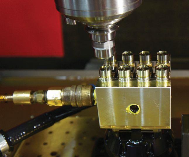
These components are inserts for expanded-beam fiber-optic cable connectors that use lenses to focus and transmit light from one optical fiber to another. The bores holding the optical fibers must be held to within +1.5/-0 microns of nominal diameter and an N4-level (0.2-micron) surface finish. Although most of the part (as well as other components for the same job) is machined on a Swiss-type lathe, operations requiring that level of precision are left to the shop’s Kern Evo machining center.
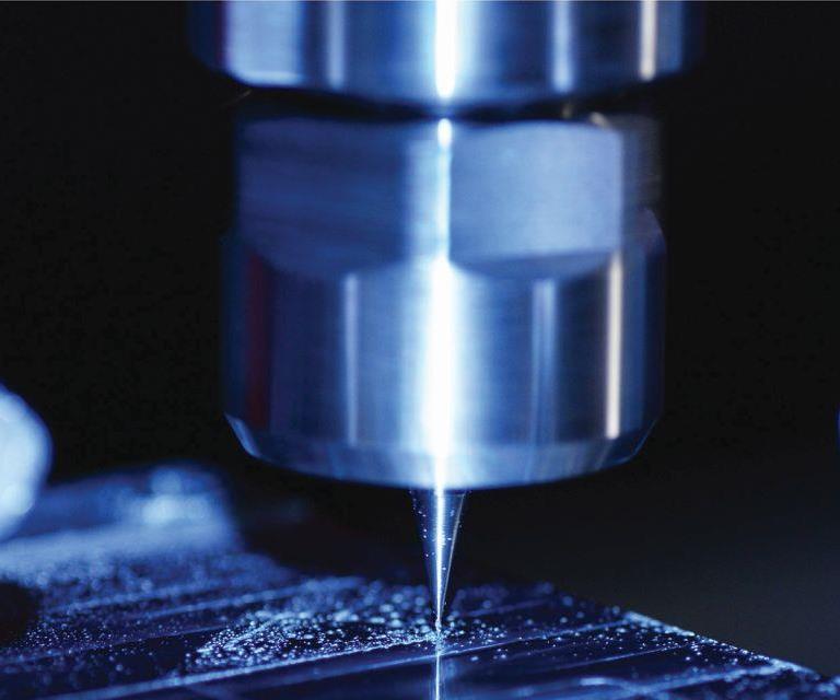
Microfluidics industry R&D applications have called for milling channels with extremely smooth finishes into plastic or, as seen here, titanium plates. Trochoidal tool paths facilitated fine control of radial depth of cut, thereby ensuring consistent cutting forces and the ability to finish both sides of this 0.006-inch-diameter channel and achieve an N4 (0.2 micron) surface finish in a single pass. For work this demanding, the shop has also been known to temporarily turn off thermal compensation in the Z axis to prevent a compensating movement from marring the surface.
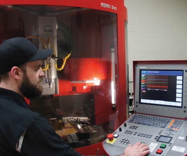
Andrew Sweeting, Integral Machining’s production manager and the chief operator of the Kern Evo, demonstrates the Heidenhain CNC’s oscilloscope. This function helps hone in on sources of error through real-time displays of how far each axis deviates from its programmed position.
A closer look at the fiber-optic connector inserts. The optical fibers are contained within ceramic sleeves, or ferrules, that fit snugly within 2.5-mm-diameter bores, which feature 3-mm counterbores on the connecting ends to accommodate the lenses.
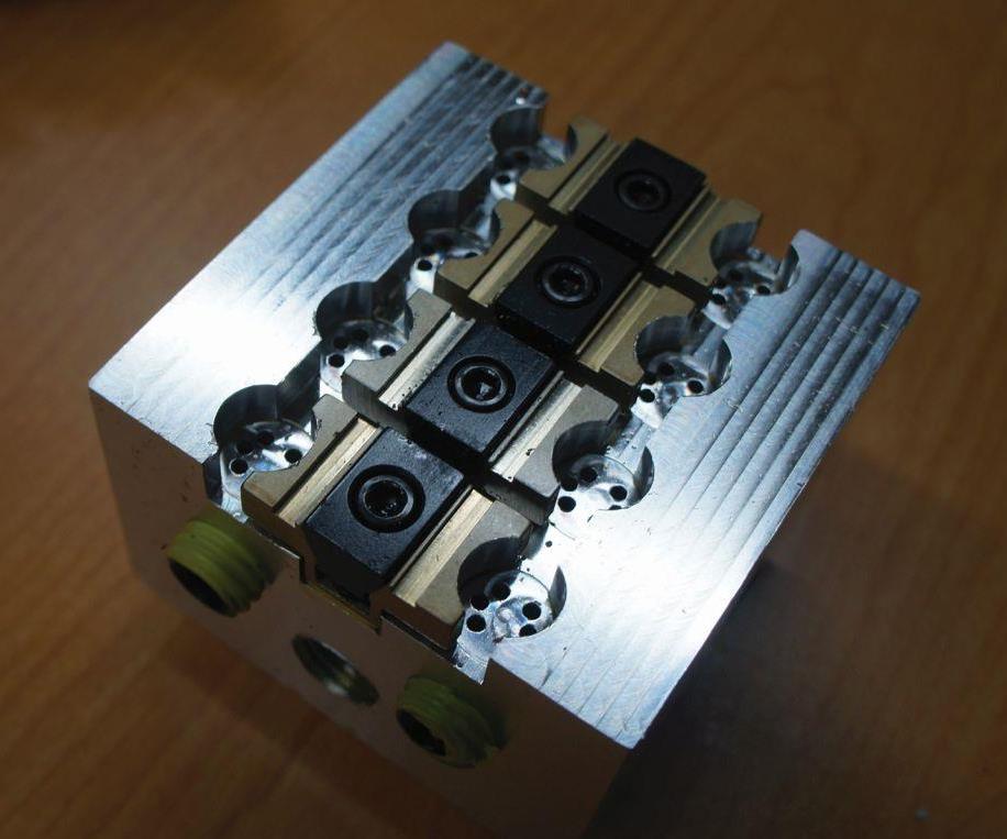
The first optic connector insert bores emerged from the machine slightly bell-shaped, a defect resulting from the cutter deflecting off chips that didn’t evacuate. This fixture features a coolant-line connection and internal channels that enable blasting fluid (and chips, which are more like powder in this case) upward through the bores. The clamps are Uniforce-brand models from Mitee-Bite. Initially purchased for consistent clamping forces that are essential to operations on the Evo, these devices have since been widely adopted throughout the shop.
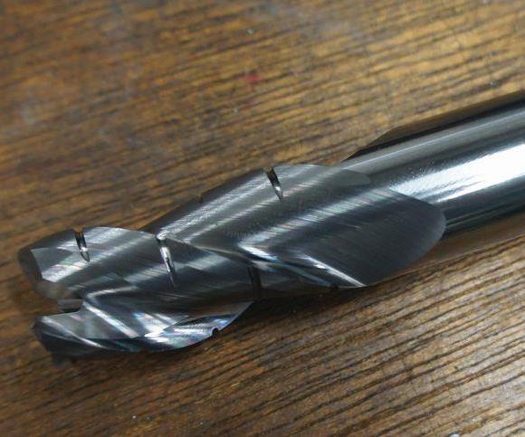
Since moving into work requiring extreme precision, Integral Machining has been using more specialized tools on other jobs as well. Designed specifically for aluminum, this Alumigator 0.5-inch-diameter end mill from G.W. Schultz Tool features variable flute geometry designed to create small chips and a polished rake to ensure chips don’t stick to the cutter.
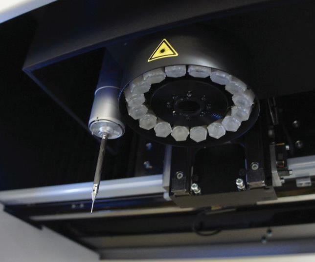
Purchased shortly after the Evo, the shop’s Zeiss O-inspect CMM offers both touch-probe and optical measurement capability. The latter is particularly useful for features too small or sensitive to reach with a probe. Even in an application like that, however, the probe might be required to indicate the workpiece if the part is not perfectly square to the camera.
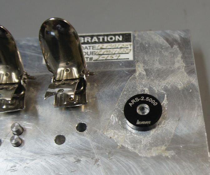
This 2.5-mm-diameter cubic zirconia ring gage was purchased for a job that required bores with particularly tight tolerances. Calibrating the CMM with artifacts that closely match the size and geometry of measured features is one of many lessons from such work that have translated to the broader shop.
Share


Integral Machining LTD has long touted its expertise in high-precision machining, but that term has taken on new meaning during the past few years. Serving customers in such industries as microfluidics and photonics has pushed this 6,000-square-foot, Toronto-area shop to institute machining processes that achieve tolerances measured in single-digit microns.
The shop’s entry into these markets was the result of a deliberate push to differentiate itself in the immediate wake of the economic downturn, says Peter Reypa, president and founder. Enter Kern Precision Inc.’s five-axis Evo, a machining center with positional accuracies of ±0.5 micron that was installed in 2010. That’s sufficient to achieve ±2 microns on the workpiece. Still, even this machine must be pushed to its limits to satisfy the stringent requirements that characterize work from the shop’s newer customers. Efforts to that end have consisted largely of eliminating even the most seemingly insignificant sources of error through environmental controls, careful calibration routines, advanced CNC functionality, and new cutting tools, software and machining strategies.


What’s more, the benefits of attaining micron-level machining capability extend beyond the opportunity to compete in a less crowded arena. Pushing the Evo has required the staff to push their own thinking, too, Mr. Reypa says, and lessons learned often translate to less demanding work in the broader shop. As a result, Integral Machining has become a more efficient and effective machining operation overall, and thus, a better partner for all customers, whatever their requirements, Mr. Reypa says.
Prepared for Precision
Integral Machining was particularly attracted to micron-tolerance work because much of the right kind of capacity was already in place before installing the Evo, Mr. Reypa says. Founded in 1989 in Oakville, Ontario, the shop has long occupied a niche in small, high-precision parts, particularly for the aerospace and medical industries. Go-to machining resources include four three-axis VMCs with aftermarket rotary fourth-axis attachments, as well as three Swiss-type lathes. Although none of these machines offer the precision of the Evo, that level of precision isn’t required for every feature of every part. In fact, only about 30 percent of jobs require micron-tolerance operations, and those operations are usually limited to a few critical features. As a result, the 11-employee shop has been able to move into new segments of work while filling capacity on more than just its most capable machining center.
That machining center has proven capable indeed since its installation in 2010, he says. The Evo’s precision begins with a C-frame construction that keeps the spindle fixed in Z and relies on table motion for all other axis travels. It also features a polymer concrete base that, according to Kern, is stiffer and more resistant to vibration than the cast iron or weldment frames typical of many machine tool designs. Glass scales and roller-seated, prestressed, prismatic linear guides contribute to machine resolution of 0.1 micron. Meanwhile, circulating water keeps all components, including the axes, spindle, electrical cabinet and coolant tank, at a constant temperature of 20°C. The electrical cabinet is separated from the rest of the machine, as is the chiller that cools the water, to prevent the heat generated by these components from affecting precision.
Installing this machine was in many ways more like setting up a piece of metrology equipment than a piece of machining equipment, says production manager Andrew Sweeting, the machine’s chief operator. Although the shop has long segregated its coordinate measuring machine (CMM) from the broader operation, accommodating the new machining center required closing off an even larger space surrounding the quality control area. The environment in this 1,100-square-foot section of the shop is tightly controlled. Temperature is held to a constant 20°C (there’s no turning down the thermostat at night here), and five hygrometers monitor humidity. To prevent yaw, pitch and other errors from creeping into the structure with continued use, Mr. Sweeting conducts a machine calibration routine every month. Kern representatives also visit approximately every 18 months to conduct an even more thorough calibration using a Heidenhain KGM grid encoder.
However, Mr. Sweeting emphasizes that even the most carefully engineered, well-maintained machine and a highly controlled environment haven’t been enough. Without learning to optimize the process for specific jobs, Integral Machining never would have been prepared to meet tolerances that match or even exceed the Evo’s advertised capabilities of ±2 microns on the part.
No Room for Error
Complementing error controls inherent to machine and environment begins with steps that are relatively simple. However, that doesn’t make them any less essential. One example is allowing the machine to warm up before cutting begins. The length of the warmup depends on the application, Mr. Sweeting says, ranging from an hour or so for workpieces that respond well to heat to all night for more demanding materials. He adds that he often warms up the smallest tools for 10 minutes or so by letting them run at operational speed until the carbide expands. To manage vibration, he sometimes posts a sign to warn operators of the VMC on the other side of the door to avoid heavy roughing while the Kern runs. “We can’t tolerate any variation,” he says.
One strategy for zeroing in on inconsistencies, including those that don’t start with the machine itself, is to measure axis deviation with the oscilloscope function of the machine’s Heidenhain iTNC530 CNC. Typically used by machine tool builders and distributors for axis tuning, the oscilloscope measures electrical signals to determine the difference between the axes’ programmed positions and actual positions. Results display as two-dimensional waveforms for each axis (Mr. Sweeting likens the display to a heart monitor).
One benefit of this feature is reduced troubleshooting time. For instance, if Y-axis motion is on target but X-axis motion is not, Mr. Sweeting might conclude that a programming error resulted in too much material being left on one side of the part. “With a 1-inch end mill, leaving an extra 0.001 inch might not make a difference, but that’s 25 percent of the diameter of a 0.004-inch end mill,” Mr. Sweeting points out.
The oscilloscope has also proven invaluable for determining “sweet spot” cutting parameters that provide the smoothest machining for various cutting tools. The basic idea is to ensure the cutting edges hit the workpieces in time with the natural frequency at which the machining center is prone to vibrate with that particular tool. In one recent instance, a manufacturer’s recommendations specified 48,000 rpm for effective cutting of microfluidic channels in Grade 5 titanium with a 0.006-inch-diameter, four-flute end mill—a speed that’s very close to the Evo’s 50,000-rpm limit. However, testing different parameters with the oscilloscope revealed that the tool would perform far better at 39,000 rpm—that is, the spindle speed at which the Z-axis line stayed flattest throughout the cut.
Pushing the Limits of Smaller Cutting Tools
Advanced CNC functionality and sweet-spot harmonics aside, running extremely tiny tools at extremely aggressive spindle speeds took some getting used to. “I’d never in my life spun a 6-thou end mill that costs $50 apiece at anything close to 50,000 rpm, and it was a bit nerve-wracking at first,” Mr. Sweeting admits.
Yet, the greater the comfort level with trying new things on the Evo, the greater the comfort level in doing so out in the broader shop as well, regardless of whether customer specifications require it. “We’re pushing the envelope a lot more,” Mr. Reypa says. For instance, he says the shop is more likely to use specialty tools in cases when it previously would have defaulted to straight-flute carbide end mills. One recent case involved roughing aluminum at 10,000 rpm and 200 inches per minute with a ¾-inch end mill designed specifically for that material. “Five or six years ago, we’d have probably used a high speed steel regrind and gone slow and steady with it,” he says.
Such experimentation has led the shop to prize certain tool characteristics that it never would have considered if it hadn’t purchased the Evo. The following outlines a few examples of those characteristics, as well as other changes driven by a more open-minded, forward-thinking attitude and greater willingness among staffers to push themselves and their equipment to new limits.
Slimmer tool necks. Virtually every end mill employed in micromachining has a reduced neck; that is, the neck of the tool is a solid cylinder that’s smaller in diameter than both the business end and the shank. This construction offers greater rigidity and strength than tools with flutes extending the entire length of the neck, because the cross section of the flutes is relatively thinner and weaker.
Strength and rigidity are critical for the tiny end mills employed on the Kern, but the broader shop also sees plenty of work that requires tools with length-to-diameter ratios that increase the risk of breakage and vibration, Mr. Sweeting says. Reduced necks also improve access to part features because they’re less likely to interfere with the cutting action, regardless of part size or tolerances.
Variable tool geometry. Success in micromachining has also led the shop to prioritize cutting tools with variable helix angles, rake angles and flute spacing. Applications on the Evo leave no room for chatter, and symmetrical end mills are particularly vulnerable, Mr. Sweeting says. Identical cutting edges create vibrations at identical frequencies, vibrations that build on one another as each successive edge strikes the workpiece. Variable-geometry tools suffer no such buildup. The number of flutes on a tool is also important. The greater the number of flutes, the less likely it is that one flute will exit the material before the next one enters it, thus creating a “hammering” action, Mr. Sweeting explains. Additionally, spreading cutting forces and chip generation among more flutes generally results in smaller chips and smoother surface finishes.
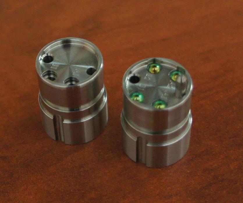
Absent tools with multiple, variably spaced and angled flutes, the shop probably couldn’t machine parts like those in the first and fourth pictures, Mr. Sweeting says. These inserts for expanded-beam fiber-optic cable connectors use the green lenses to focus and transmit light from one optical fiber to another. Finish-machining the bores that hold the lenses and optical fibers to an N4-level (0.2-micron) surface finish involved using a 2-mm-diameter, 10-mm-long, three-flute end mill to shave off only 100 microns of material in a helical motion. Work in the broader shop isn’t nearly as demanding, but the shop often leverages such cutters to boost the performance of any suitable operation.
Same tool, multiple features. One of the most difficult challenges associated with the fiber-optic connector inserts was ensuring the lenses seated in the counter-bored holes were lined up well enough. More specifically, the problem was ensuring concentricity between the 2.5-mm-diameter bores and the 3-mm-diameter counterbores. With a helical tool path, the counterbores and bores could be machined with the same end mill. This strategy kept the lenses straight enough to keep light loss within specification (no more than 1.5 dB).
Runout, temperature, wear and other factors affecting the cut can vary with different tools, however carefully mounted in the toolholders and however exacting the tool-changing mechanism, Mr. Sweeting explains about the success of this strategy. Although particularly impactful for operations on the Evo, the same principle applies at any scale.
New tool paths. Using the same tool for multiple features wouldn’t work very well without efforts to maximize tool life, and Mr. Sweeting credits 3D Systems’ Cimatron CAM software for much of the gain. Initially purchased to replace a system that didn’t offer sufficient resolution or 3D capability for operations on the Evo, this CAM package facilitates the use of smoother tool paths that provide better control over cutting forces. One example is trochoidal milling, a slot-milling strategy employed for parts like the microfluidic test plate in the second picture. Feeding the tool in a looping, curlicue pattern enables precise control of radial depth of cut, a particular concern when the goal is to mill the entire slot with the same cutter. With surface finish of 0.2 micron, changing tools would have been risky on that job. It also likely would have been less efficient, he adds.
Although instances of using trochoidal milling in the broader shop are rare, the same principles have been applied to improve tool life and productivity there as well. For example, Mr. Sweeting credits Volumill, a toolpath engine within the software, for generating tool paths that keep the load on the cutting tool and spindle within programmed limits by avoiding sharp changes in direction or tool engagement.
Consistent machine motion. Ensuring proper positioning for patterns of features, whether relative to one another or any particular datum, can be particularly difficult for work that requires the Evo. For example, the positions of the bores on the fiber-optic connector inserts must be held within ±1.5 microns. In scenarios like this, programs for the Kern always direct the machine to return to a center position after drilling each hole, rather than moving from one hole to another in sequence. This strategy ensures that X- and Y-axis movement to and from each hole—and by extension, acceleration, deceleration, breaking distance, backlash and so forth—is as consistent as possible. Although not usually necessary for work that doesn’t require the precision of the Evo, this strategy always provides peace of mind when feature position is critical, Mr. Sweeting says, particularly when multiple tool changes or other factors add potential for variation.
Broader Evo-lution
Technology and process changes spurred by adding extreme-precision parts to the shop’s mix of go beyond machining operations. For instance, the previous CMM simply wasn’t sufficient for micron-tolerance work, Mr. Reypa says. Today, the shop uses an O-Inspect multi-sensor system (optical and touch probe) from Carl Zeiss Industrial Metrology. As was the case with the Evo, measuring difficult work on this machine spurred across-the-board improvements in quality control.
For example, the 2.5-mm-diameter cubic zirconia ring gage in the last picture was purchased for one of the shop’s first applications requiring single-digit-micron tolerances on small bores. Calibrating the machine with a larger artifact wasn’t enough to ensure consistent measurements. The lesson inherent to that application—that the artifact used for calibration should match the geometry and size of the feature to be measured as closely as possible—has since been applied on a number of jobs in the broader shop. “If we need to check a bore to a couple of tenths with a snap gage, we might get a special ring gage made that’s accurate to within five decimal places. Then we know we’re beyond accurate,” Mr. Reypa says.
As lessons learned in extreme-precision operations continue to percolate through the shop, Mr. Reypa, Mr. Sweeting and crew are eyeing their next step. In fact, Mr. Reypa says they might have already purchased a Kern Micro, the builder’s successor to the Evo, if it weren’t for a less-than-favorable exchange rate between the Eurozone and Canada. Whatever the future holds, Integral Machining is eager to expand its capability and capacity for jobs requiring tolerances measured in single-digit microns. If past experience is any indication, more of that work will pay off not only in direct revenues, but in a more capable shop as a whole.


Related Content

Additive/Subtractive Hybrid CNC Machine Tools Continue to Make Gains (Includes Video)
The hybrid machine tool is an idea that continues to advance. Two important developments of recent years expand the possibilities for this platform.
Read More
DN Solutions America Unveils Impressive Chicago Technical Center at IMTS 2024
New tech center is serving as a cutting-edge showroom and a technological hub for advanced machining applications.
Read More
Results-Driven Innovation on Display at Mazak's DISCOVER 25
DISCOVER 25 attendees will enjoy keynotes and panel presentations, and have a chance to tour the Mazak iSMART Factory where the company “uses Mazaks to make Mazaks.”
Read More
The Cut Scene: The Finer Details of Large-Format Machining
Small details and features can have an outsized impact on large parts, such as Barbco’s collapsible utility drill head.
Read MoreRead Next

Effective Plastic Machining Requires Effective Chip Control
Clean, burr-free cutting is fundamental to competitiveness for a shop that specializes in micro-machining complex geometry from some of the softest materials in the industry.
Read More
Watchmaking: A Machinist’s View
Old-world craftsmanship combines with precision machining on a vertical machining center and Swiss-type lathe to produce some of the only U.S.-made mechanical wristwatch movements.
Read More
OEM Tour Video: Lean Manufacturing for Measurement and Metrology
How can a facility that requires manual work for some long-standing parts be made more efficient? Join us as we look inside The L. S. Starrett Company’s headquarters in Athol, Massachusetts, and see how this long-established OEM is updating its processes.
Read More