
Moving from Contact to Noncontact Surface Analysis
2D measurement systems check specific lines for roughness quality, while a 3D surface analysis provides assurance for a broader area — which can avoid costly process disruptions and bonding failure.

Share


Computer-aided design (CAD) has dramatically sped up the process of getting ideas into the marketplace. These days, products ranging from children’s toys to passenger jets are completely designed in a virtual environment before a single part is manufactured.
When part surfaces are the user’s first impression, or they need to interact with surfaces on mating parts or perform a particular function, the real design engineering begins. Since we know that surface finish affects the way parts reflect light, interact with other parts and even distribute lubrication, measuring surface finish with the correct procedure is important.


For nearly 100 years, 2D roughness and waviness analyses have been an integral part of quality control. Whether the requirement was for a roughness parameter using a skidded probing system or for waviness/profile with a skidless measurement system, many systems were available. One or more traces were made of the surface using a 2D tool to record the key characteristics needed for roughness/waviness measurements. The resulting surface plot provided deviations across a flat plane when viewed perpendicularly, and by using a specific surface/waviness/profile analysis, an indication of the surface was provided.
These 2D systems are still the most commonly used tools for surface analysis because of their value, portability, ease of operation and common language between industry standards and manufacturers. However, as surface tolerances have shrunk to the sub-nanometer level, new manufacturing processes do not create the same “pattern” as created by a typical machine tool. Also, there are greater demands for designer coatings, bonding, lubrication, friction and more, meaning a single profile may not provide enough data to analyze the surface area. This is where 3D surface measurement can provide the analysis needed.
Today, optical surface analysis systems using vision, confocal image analysis and interferometry are available. 3D measurements using optical measuring techniques are useful when there is a requirement to focus on functional structures such as protrusions or depressions, and for determining core parameters or the load-bearing ability of the surface. A non-destructive, material-independent surface quantification is also required when evaluating inhomogeneous and porous surfaces such as ceramics and cast materials.
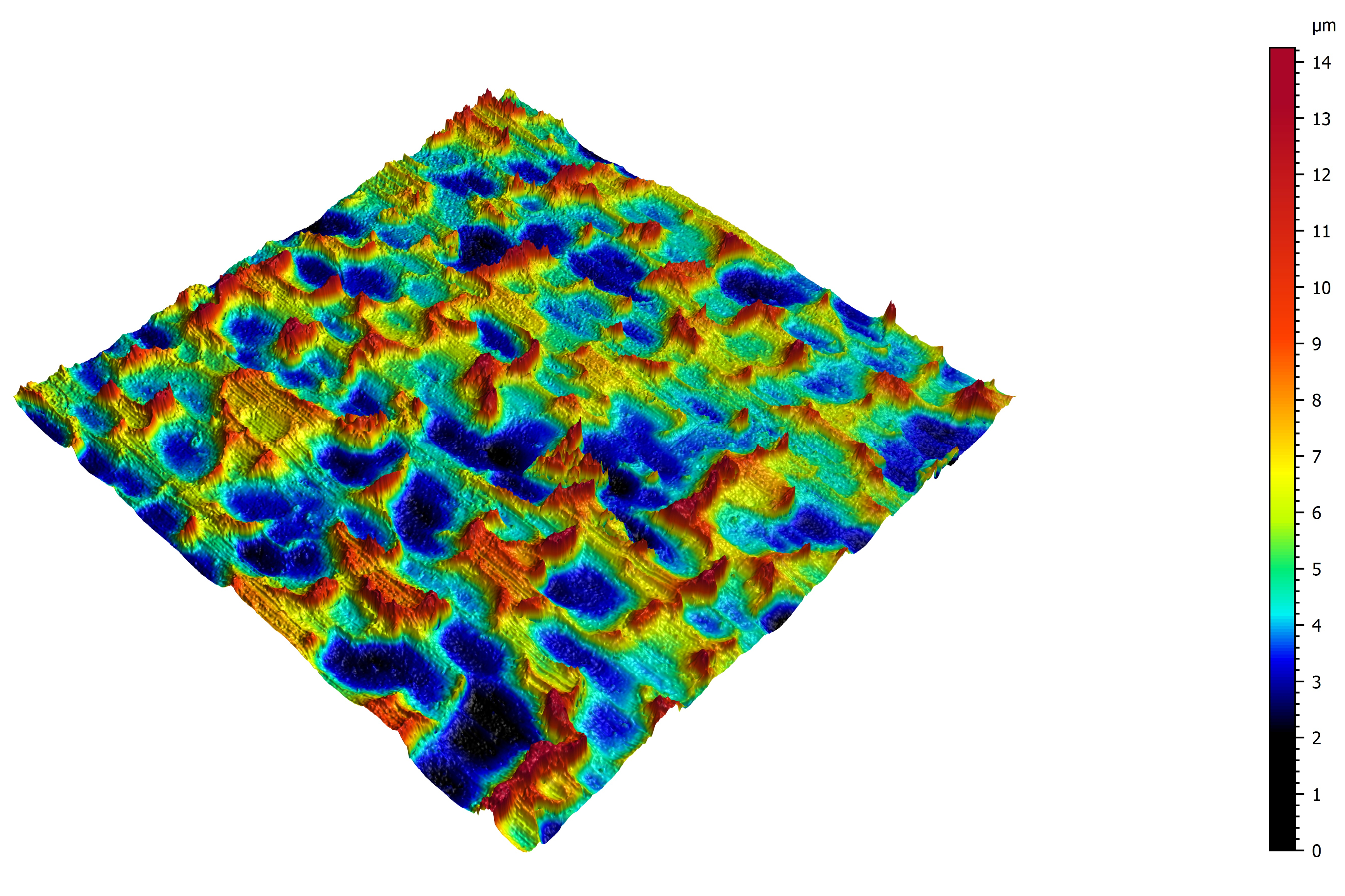
3D optical surface systems provide highly detailed information about the height, intensity and color across every point in the measurement area on a topographical map that enables the operator to obtain a true representation of the surface. By providing greater statistical certainty with larger dataset sizes, systems deliver micron and nanometer-resolution surface finish and micro-geometry information, including 2D and 3D surface roughness, bearing area, flatness, depth and so much more.
The appearance of product surfaces will make or break a buying decision in high-end electronics, automobiles or even household touch surfaces. When applying coatings, paint or adhesives, surfaces must have a certain, specified roughness to ensure a sustainable bonding. With a 2D measurement, only specific lines are checked for roughness quality, while a 3D surface analysis provides assurance for a broader area — which can avoid costly process disruptions and bonding failure.
3D measurement is currently used in the laboratories or production environments of cutting-edge industries such as aerospace, automotive, electrical engineering, mechanical engineering, medical technology, optics and renewable energy.
International standards provide the steps required to perform a roughness measurement so that everyone making the test follows the same rules and achieves the same result. While many of the measurement parameters for 2D and 3D are the same, some specific ones are only possible with 3D measurement (since these surface parameters require an areal versus a single profile).
ISO 4287 and ISO 13565 are common 2D surface measurement standards. ISO 4287 defines 2D technology surface texture using stylus profilometers for surface measurement and details the rules and procedures for the assessment, and typically records profiles with lengths of several millimeters. ISO 13565 details a filtering method for use with surfaces that have stratified functional properties.
The basis for worldwide traceability for 3D is defined by the ISO 25178 standard, which details 3D surface texture parameters and the methods for identifying them. This is the first international standard to consider both the measurement and specification of 3D surface textures and cover noncontact measurement techniques.
In summary, 2D surface measurement is an excellent choice for quick surface finish validation of well-understood products and processes. On the other hand, 3D noncontact measurements may be the better choice when the surface is technically complex, a higher statistical certainty is required or the material requires a noncontact method.


.png;maxWidth=300;quality=90;format=webp)


Related Content

4 Ways to Establish Machine Accuracy
Understanding all the things that contribute to a machine’s full potential accuracy will inform what to prioritize when fine-tuning the machine.
Read More
Understanding Structured Light Scanning Measurements
Structured light scanning is used to create a digital twin of a manufactured part, but we must understand the measurement reproducibility to best use the data.
Read More
A Balancing Act for Differential Gaging
Differential gaging measures using two devices, which has advantages over standard, comparative measurements using a single sensing head. These include the ability to measure size without regard to position.
Read More
The Many Ways of Measuring Thickness
While it may seem to be a straightforward check, there are many approaches to measuring thickness that are determined by the requirements of the part.
Read MoreRead Next

OEM Tour Video: Lean Manufacturing for Measurement and Metrology
How can a facility that requires manual work for some long-standing parts be made more efficient? Join us as we look inside The L. S. Starrett Company’s headquarters in Athol, Massachusetts, and see how this long-established OEM is updating its processes.
Read More