
Reading What the Dial Indicator Is Saying
Dial indicators provide good value for their resolution. With a glance, one can quickly determine if the part is larger or smaller than the master setting and by a degree of how much.

Share


Dial indicators — also known as dial gages, clocks, comparators or just indicators — are widely used as basic gages for measuring linear dimensions. Dial indicators have been around since the early 1900s. While digital indicators may be gathering more attention recently, dial indicators are unlikely to disappear any time soon. Dial indicators provide good value for their resolution. Experienced users like them because the analog dial gives a sense of direction and scale. With a glance, one can quickly determine if the part is larger or smaller than the master setting and by a degree of how much. Almost no thinking is involved. With the added capability of tolerance hands, the user can simply check if the indicator’s needle is within the tolerance bands and then move on to the next part.
Many dial indicators have a very short measuring range and thus are more apt to be used as a comparative device — comparing the part to a known master. However, dial indicators with a long range can cross over to become a measuring instrument and directly read the size of the part over the reference surface.


There is always a fresh set of users who may be seeing a dial indicator for the first time. Even though these indicators are relatively basic tools, new users require some knowledge to read them properly.
Dial indicators come in various sizes, ranges and resolutions. All translate variations (through the internal movement of a rack) into dial readings. Some will indicate dimensional variations as small as 0.00005 inch. They can have balanced or continuous dials, and some types can even work backward based on the application. All these options are available because the goal of the indicator is to enable the user to read it as easily as possible without requiring too much interpretation.
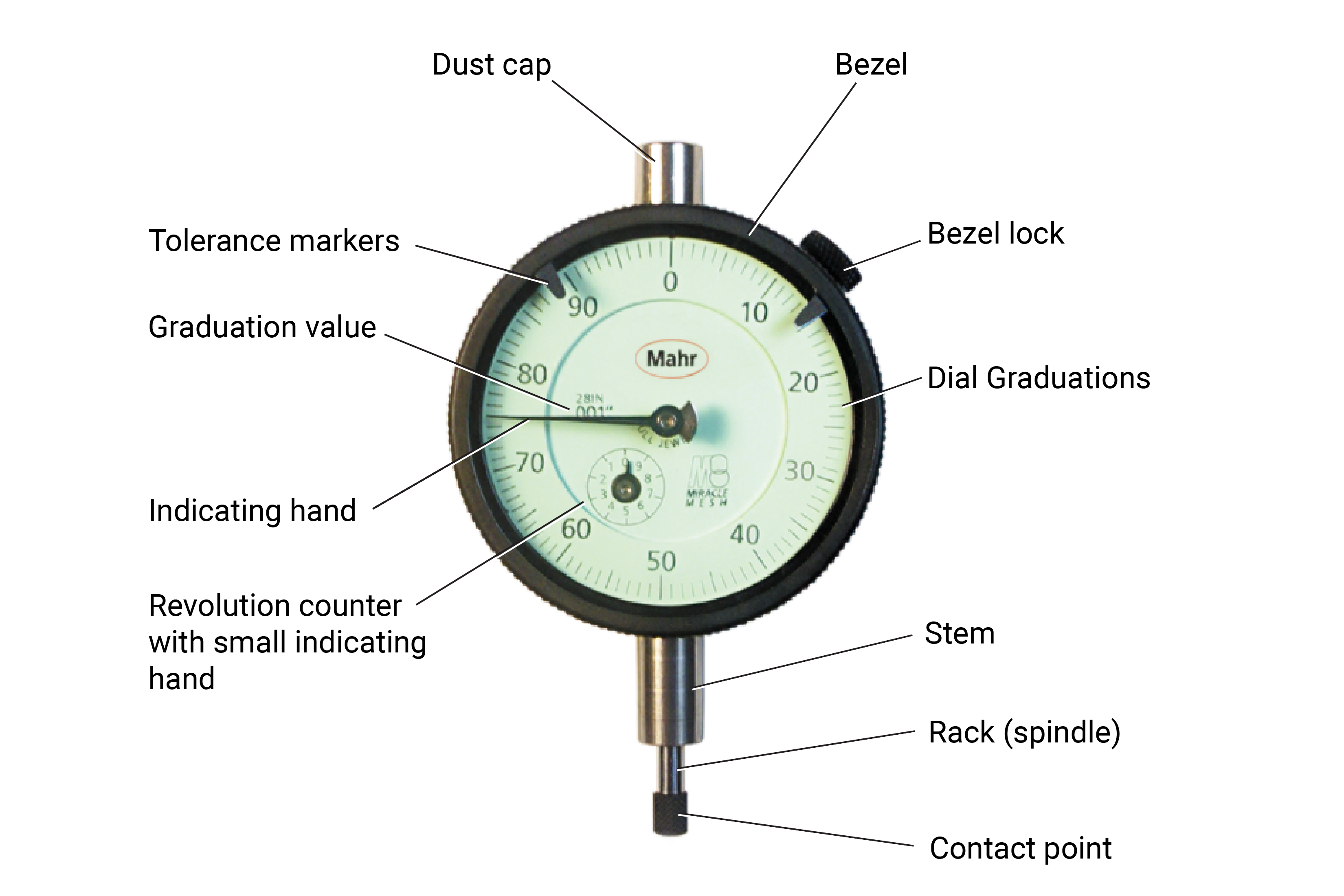
When first using a dial indicator, it is wise to give it the once over before putting it into use. Holding the dial indicator in your hand, press the rack to ensure it is moving smoothly and not binding or sticking. Then start to take a closer look at it. The dial will have the graduation value printed on it — such as 0.001 inch. Slowly move the plunger in and observe the rotation of the hand. Most indicators will rotate clockwise (indicating a larger value with inward rack movement).
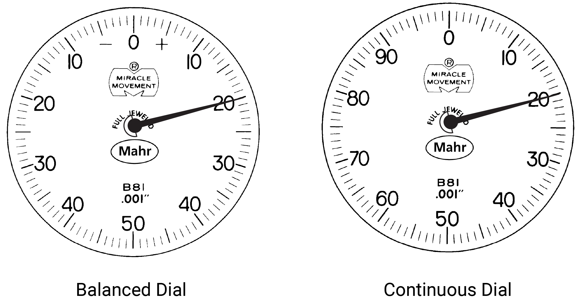
Also observe whether this is a balanced or continuous dial. A balanced dial with “+” on the right is the most common for comparative indicators. From the pictures above, we can say that this indicator has a 0.001-inch resolution, and since there are 100 graduations, the measuring range per revolution is 100 times 0.001 inch to equal 0.1 inch. Typically, an American Gage Design (AGD) indicator will have 2.5 revolutions, and in this example 0.250-inch measuring range. In some cases, these indicators will have a second, smaller hand indicating the number of revolutions the hand has moved. This can be a valuable tool to prevent misreading the indicator.
Returning to the analog watch comparison, with this dial configuration, users will need to adjust the gaging application and indicator to have the master zero setting point at the 12 o’clock position or “0” on the dial. Most dial indicators are then used in a comparative mode using a balanced dial, with minus (-) readings on the left of 0 and plus (+) readings on the right of 0.
To read this 0.001 dial indicator, having a balance dial and plus on the right is fairly straightforward. From the starting point (0 reading), to read the deviation, simply multiply the number of grads by .001 inch. For example, if the hand of the indicator was on the 20, you would multiply 20 times 0.001 inch to equal 0.020 inch. It’s easy to see that every ten grads equal 0.01 inch, and reading the values fast starts to get easy.
When using the tolerance markers, the goal is that the plus and minus tolerances are in the range of the dial’s ten and two o’clock positions. At the ten-two position, about 20% of the dial is large enough to view the intolerance position easily. There are also large-approach and over-tolerance ranges to see the work coming into tolerance, similar to the analog feature on the dial watch mentioned above. This is part of the reason for such a variety of ranges and resolutions of dial indicators.
Dial indicators are not apt to ride into the sunset quite yet. So, when you come across one, pick it up and get familiar with what it is telling you.


Related Content

How to Determine the Currently Active Work Offset Number
Determining the currently active work offset number is practical when the program zero point is changing between workpieces in a production run.
Read More
How to Mitigate Risk in Your Manufacturing Process or Design
Use a Failure Mode and Effect Analysis (FMEA) form as a proactive way to evaluate a manufacturing process or design.
Read More
4 Manufacturing Trends That Cannot Be Ignored
The next five years will present their own unique set of challenges, and shops can alleviate them by embracing these technologies and trends.
Read More
How to Evaluate Measurement Uncertainty
Manufacturing and measurement are closely coupled. An important consideration for the use of measurement results is the associated measurement uncertainty. This article describes common metrology terms and provides an example uncertainty analysis.
Read MoreRead Next

OEM Tour Video: Lean Manufacturing for Measurement and Metrology
How can a facility that requires manual work for some long-standing parts be made more efficient? Join us as we look inside The L. S. Starrett Company’s headquarters in Athol, Massachusetts, and see how this long-established OEM is updating its processes.
Read More