
The Many Ways of Measuring Thickness
While it may seem to be a straightforward check, there are many approaches to measuring thickness that are determined by the requirements of the part.

Share


The measurement of thickness is a common one. When I refer to thickness, I typically think of a piece of film, paper or even sheet metal less than a couple of millimeters thick. It is a length measurement, but just a different way of handling it. It seems like this would be a straightforward check; however, there are many approaches to measuring thickness, depending on the requirements of the part.
Whether it’s the thickness of a piece of sheet metal, a silicon wafer, a latex glove or photographic film, we are usually measuring the distance between two parallel surfaces. Accurately determining the length of a line that is perpendicular to two parallel surfaces has everything to do with how the gage contacts the part.


Some of the most common tools include calipers, micrometers, thickness gages, air thickness gages and motorized gages, with many variations of each. They range in price and complexity from a few hundred dollars for a standard handheld tool to a few thousand dollars for custom-built applications. One important consideration that makes each of these solutions different from the others is how the gage contacts the part.
One could start with the basic, trusty digital caliper. This certainly is an option; however, there are a few things going against it. Besides maybe not having the correct resolution for the tolerance of the film, the jaws are long, meaning parallelism and operator influence will affect the results.
A handheld, digital micrometer is a simple, low-cost method for measuring the thickness of a piece of sheet metal, for example, which is relatively stiff and thick, and provides a lot of measurement range. With flat and parallel contacts and constant gaging force applied with the friction or ratchet drive, the micrometer can self-align to the part for a fast and accurate reading. A potential problem with the self-aligning flat contacts of the micrometer is that they can bridge across and “average out” minute variations in thickness.
Also, with a standard micrometer, the spindle will rotate as the sensitive contact is brought onto the film. This can cause twisting and even damage the film material. A digital micrometer with a sliding spindle is much better for these applications. While micrometers can offer good resolution and parallel surfaces over a small area, different solutions may be required if tolerances are tighter.
Portable digital thickness gages raise the ante on the resolution by combining a flat anvil-type reference surface on the bottom with a radiused (ball) measurement contact, preferably a lapped and parallel contact on the top. This would be a good gage for a narrow strip of photographic film where a spot check of thickness is required.
In some cases, the part may be so susceptible to scratching or marring that any amount of gaging contact could destroy it. An air thickness gaging system is a noncontact solution that directs thin, precision-aligned, opposing streams to each side of the part, which is held perpendicular to the air streams on a ground base.
The gage measures back pressure on each of the air streams. This noncontact technique provides a means of sliding the part around to measure thickness variation. The air provides enough cushion to help float the part as it is repositioned. The use of differential probing provides fast, accurate measurement regardless of where the part is positioned. Most importantly, the part is not damaged by the gage contacts.
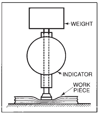
Photo Credit: Mahr Inc.
Many soft, compressible parts have rigid, standardized specifications for how they are to be measured. In such cases, the design of the compressible material thickness gage will frequently take into consideration the size and shape of the contact along with the gaging pressure applied to the part.
Usually, the gaging pressure is defined as a dead load weight to ensure constant force over the full range of measurement, and the radius of the flat/parallel contacts is also noted. This ensures a known gaging force for the area of the contacts. With this standard, any facility around the globe will get the same results on the compressible material.
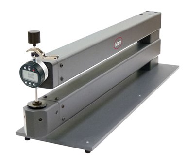
For small-size films being measured, the above portable or bench-mounted gages may do the job. It is not uncommon, however, to see sheets of film a meter or more square, and the edge thickness is the same in the middle of the parts — which also needs to be verified. For these applications, custom gage solutions with either long reach or very large bases where the part can be moved around between a set of retractable contacts will allow for full inspection.
As you can see, the method of probe contact is a very helpful way to consider how to set up thickness-gaging systems across a wide range of applications. Choosing the right approach can dramatically decrease the chance of inadvertently making a bad measurement.


Related Content

Using Air to Measure Squareness
Though most frequently used for diameter measurements, an air plug and platen can be readily configured to measure perpendicularity.
Read More
A 100-Year-Old Measurement Tool That is Still Used Today
The reed mechanism was a breakthrough in high-precision measurement and is still used today for sub-micron or even nanometer resolution applications.
Read More
4 Ways to Establish Machine Accuracy
Understanding all the things that contribute to a machine’s full potential accuracy will inform what to prioritize when fine-tuning the machine.
Read More
Understanding Structured Light Scanning Measurements
Structured light scanning is used to create a digital twin of a manufactured part, but we must understand the measurement reproducibility to best use the data.
Read More