
Tool Certainty
For GKN Aerospace to overcome tool-related variations on its largest milling machines, it had to confront error sources that go unnoticed in many shops.
Data is electronically written to the tags on the toolholders during presetting.
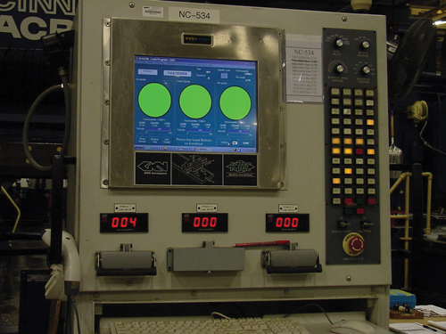
Only when the CNC display shows green lights for all three spindles is the program able to proceed.
Scanning data tags at the machine not only confirms that the correct tools have been loaded, but also enables GKN’s system to automatically offset the NC program for a specific tool set.
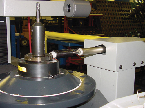
The data tag is scanned for a new tool loaded in one of the gantry milling machines.
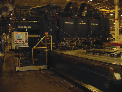
Twenty-seven of the three-spindle gantry machines such as this one have been rebuilt so far.
Share


You could stand on a catwalk above the production floor at GKN Aerospace in St. Louis, Missouri, and see the progress of multi-spindle milling machines being rebuilt in this facility. The renewed machines are all blue.
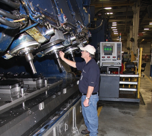
These huge machines produce large aircraft parts, with their three-spindle gantries milling three parts at a time out of aluminum or titanium. Typical bed size for one of these machines is 13 feet wide by 90 feet long. The machines are systematically being rebuilt, with the hardware refurbished and the controls replaced—and the final step in each of these rebuilds is to repaint the machine a rich blue. Now, with 27 of the 54 gantry machines having been rebuilt this way, the investment has been going on long enough that the deep blue is starting to dominate the facility.


The investment has been going on long enough to affect the facility in another significant way, too. GKN came to a conclusion that highlighted the very value of all this work. Specifically, the plant realized that the full potential benefit of the investment in machine rebuilding would only be obtained once the plant got its tool management under control.
Now, even as the gantry rebuilding continues, GKN has put in place a new tool management system that dramatically changes the way the facility assigns, organizes and even loads the tooling for these machines.
Getting to this point wasn’t easy. Tool-related errors have always seemed like an inevitable part of the process for machining the gantry machines’ most complex parts. Any of these parts might require hundreds of tools, and tool errors could be the result of not just faulty tool setups, but also faulty tool manufacturing (more on that below). When such tool errors were small, they might produce defects to be corrected later. When errors were large, they were usually caught before they could damage the part—but not often enough. On one important occasion, a tooling error caused an overcut that resulted in hundreds of thousands of dollars worth of titanium forgings being scrapped.
In the wake of this event, GKN’s corporate management asked: What would it take to make sure that this never happens again?
“Automatic presetting” was the initial answer from the plant’s staff. That is, the plant needed sophisticated enough tool measurement to quickly perform a detailed inspection of every tool.
But no. Further reflection and discussion among the St. Louis personnel revealed that presetting alone wouldn’t be enough. A tool measured as wrong by the presetter might still be taken into production. A tool measured as right by the presetter might still be used with an erroneous offset or program. What the plant really needed was a system that could not just detect tooling-related errors, but also stop them. What the plant needed, in short, was a system for ensuring that the correct tools with the correct offsets were loaded for the correct machining operations every single time.
A team in St. Louis that included engineers, programmers and machinists began to meet regularly to work toward a system that would accomplish exactly this.
The solution, in the end, required much more than presetters. It required the use of hardware, software and new procedures within an interlocking strategy. Some elements of the new system are detailed below.
Overall, though, one of the most striking aspects of the system as it operates today is the way that it captures and corrects for variables that many shops don’t even recognize as variables. Unseen human error in the way tools are made, set up or loaded in the machine affects the accuracy of machined parts every day. The variations are often treated as simply part of the “background” inaccuracy of the shop. While the peril of these variations may be magnified at GKN because of the size and expense of its parts, a tool-management system that incorporates at least some of the elements below could potentially benefit almost any production machining facility.
In fact, effective tool management actually begins well in advance of the tool presetting that GKN initially saw as important. It begins instead in the engineering department, where the tools are specified in the first place.
However, to describe this system, it’s helpful to start at the end—looking first at the moment when the assembled tooling arrives complete and ready for use at the machine.
Matching Tooling
A multiple-spindle gantry machine places one particularly striking demand on its tooling. It requires all three spindles to have identical tools.
In the far more typical milling process involving just one spindle, the dimensions of the tool are free to vary. Tool offsets can let the one-spindle machine account for whatever the dimensions of the tool happen to be. Not so for a three-spindle machine. To run three identical parts, all three tools need to have the same dimensions within a narrow band of consistency. As a result, tooling for the three-spindle machines is set to particular offset dimensions—not the other way around.
The complexity goes even beyond this, because a tool might have different dimensions throughout its useful life. For a milling tool, regrinds affect the diameter. GKN formerly handled this variable by running different NC programs to accommodate different regrind increments of the tools. The different programs were particularly important for five-axis machining, where—because of the influence of angles and trigonometry—changes in tool dimension can have complex effects on the tool path. In order to use these programs that were based on different regrinds, worn tools were ground down to fit the regrind increments of the programs, whether the tools needed that much grinding or not.
One final variable is time. All three tools need at least enough remaining life to be able to last through the cut together. Tools therefore have to match not only in their dimensions, but also in their durations.
Thus, the range of the potential error sources was large indeed. For every particular cut, human beings had to make sure to run a matching set of tools with enough remaining life, using a program written for the regrind state of those tools.
The best machinists navigated these variables well.
But the system that is in place now is better. It guards against all of the potential errors automatically—and it does so with a speed and effectiveness that is the same for any operator, regardless of whether a new hire or a veteran machinist happens to be the one at the machine.
Data Tags
The tool that arrives at the machine now brings its own tool data along with it. Each tool assembly includes a tag for storing electronic data on the toolholder—part of a tool identification system supplied by Balluff. When loading a new set of tools in the three spindles, the operator now just touches each of the tags with a small scanner to let the machine’s CNC confirm that each tool is correct for the job, and that it matches the other two tools in the set.
Part of the rebuild work for the gantry machines has been to install identical CNCs on every one. These numerous control retrofits were performed by KRC Machine Tool Services. In the past, the plant did not have this commonality of control, but now, thanks to KRC, all the rebuilt machines have identical, modern Fanuc CNCs. These new controls run various software tools that have been customized by GKN—one of which is a graphic display that makes tool-scanning results immediately clear to the operator. Only when this display shows green lights for all three spindles is the program able to proceed.
Posted Programs
The use of different NC programs for different regrind increments is not necessary now, thanks to software developed by Numerical Control Software Solutions. This software—“NCTC,” for NC Tool Compensation—takes the five-axis machining program in its postprocessed state and writes offsets for this code appropriate to the actual tool dimensions. Logic in the software looks at the existing moves of the posted file to determine the intent of each move. The offsets then realize that intent using the actual, smaller, reground tool.
Just after the tool set is loaded at the machine, GKN applies this software to offset only the segment of code associated with that particular tool number. The affected code is then deleted as soon as the cut runs. In this way, every particular set of tools gets unique movement that is created solely for those tools, solely for that particular moment in time.
This novel software is one of the seemingly magical aspects of the new GKN system. The algorithms that are able to diagnose the “intent” of the postprocessed code required significant development time, but the result of that work is software capable of accurately and automatically changing the movement of the tool where needed. A simple example is modifying a 90-degree turn to maintain an intended radius when the tool no longer has that radius itself. Where the tool diameter is too small, the NCTC software duplicates the nominal cutter’s corner-radius results by arc-filling the offset—thereby producing tool motion that follows a curve instead of a right-angle turn. In five-axis machining, the trigonometry resulting from tool diameter variations can require offsets to be applied in similarly complex ways—again for the purpose of maintaining precisely the same machining results that the full-size tool would have achieved.
The ability to account for the tool’s regrind state in this way eliminates confusion among the different programs that the shop previously used. It also saves considerable tooling cost. Cutting tools are still reground in increments, but only to produce matching reground sets. No longer are tools ground down to the much larger increments of 0.020 inch, 0.040 inch and so on—increments that once characterized the different NC programs. As a result, many of the tools used routinely on the gantries now see dramatically longer life.
Presetting
The tool crib of the GKN facility is where the plant’s two new Zoller presetters are used. Before any tooling assembly is sent to the shop floor, it is quickly inspected in an automatic routine created for that specific tool number. A tool gets its measured data written to the data tag, but only if the tool passes inspection.
Tool assemblies can fail this inspection for various reasons, but one of the surprises of implementing the system has been to find how often new tools fail because of errors related to the manufacture of the tool. An erroneous cutting edge radius is the most common reason for this failure, but various other geometry errors have been discovered. In one extreme case, a new solid-body end mill, fresh from the packaging, had a ground-in runout error of 0.015 inch.
The percentage of these defective tools is small, but with the gantry machines accounting for 400 to 500 tool setups per day, even a small percentage of tools can amount to a sizable number. Collecting rejected tools for return to suppliers is also a routine part of the new
process.
Error Avoidance
Yet for all the potential problems caught by the presetters, even more potential problems are now discovered and avoided well before the tool is ever assembled. An integrated database unites tool data throughout the facility, and the plant’s engineering department now makes use of the data in ways that have made defect-free parts common. In fact, even first-article parts tend to run without defects now.
Software from TDM Systems captures all the shop’s tooling information. Atop this software, the plant has developed various utilities that both simplify programming and safeguard the machining processes.
For example, a custom search utility allows programmers to search the shop’s 1,600 standard tool assemblies by tool type, machine type, workpiece material, tool geometry and various other parameters. This ensures that the right standard tool for any job can be discovered quickly. The system avoids the inefficiency of specifying a new tool for a cut when an existing tool the plant already has in stock will do the job. In fact, only a few engineers can enter new standard tools to the shop’s system as it now exists—meaning that one of them has to be persuaded that the new tool is necessary before any new tool is added.
Another GKN-developed utility draws complete tool assembly data into the shop’s CAD/CAM software, so the tools and toolholders can be modeled together, as opposed to modeling just the tools. This permits a reliable initial verification of the program before it is posted for full verification in CGTech’s Vericut software. In Vericut, the NC program is then run not just at the tool’s nominal value, but also its most extreme regrind value. If that extreme regrind produces interference, then the minimum tool diameter is modified in the shopwide system so the tool can never proceed to production at a size below this diameter.
Defect Free
One illustration of the result of all of this new control over tooling involved an aircraft bulkhead part. This existing part became new again when the plant obtained permission from the customer to reengineer the machining process. Improving the long-established process allowed GKN to rough and finish the part in less time than finishing alone used to require. Just as significantly, the newly programmed part was run with zero defects the very first time the new process was tried.
Machining with zero defects can be challenging enough in full production. To run a large and complex first-article part with zero defects was noteworthy to say the least. The achievement says something about the nature of all those minor defects that have long been accepted and corrected as a routine part of the process.
Specifically, the ability to run defect-free today—with the new tool management system in place—shows just how many of those long-standing sources of variation have been directly related to the tooling all along.


Related Content

How I Made It: Nushrat Ahmed: CNC Swiss Operator
By day, 21-year-old Nushrat Ahmed is a CNC Swiss operator making automotive parts. By night, she handcrafts crocheted items.
Read More
How Proper Scheduling Leads to a Successful Machine Shop
Proper scheduling of jobs is paramount when it comes to running an efficient machine shop.
Read More
How I Made It: Trevor Hirschi, Instructor, Bridgerland Technical College
Student, operator, instructor, shop owner — Trevor Hirschi’s many roles have enabled him to understand both the technical and creative sides of manufacturing.
Read More
Finding the Human Connections in Human Resources
By working with its employees and its community, Win-Tech has found unexpected opportunities for employee retention and recruitment.
Read MoreRead Next

A Practical Guide To Presetters
Tool measurement devices help shops save time, control runout and improve tool management.
Read More
OEM Tour Video: Lean Manufacturing for Measurement and Metrology
How can a facility that requires manual work for some long-standing parts be made more efficient? Join us as we look inside The L. S. Starrett Company’s headquarters in Athol, Massachusetts, and see how this long-established OEM is updating its processes.
Read More