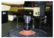
A Shop Preset For Productivity
The tool presetters at this shop are interfaced to its computerized tool inventory system as well as linked to the machine tools for direct downloading of offset data. Digital image processing at the presetters is the key.
Share


From the beginning of January to the beginning of December 1999, the tool crib serving Waters Corporation's Machining Operations had distributed a total of 72,056 individual tooling items. That represents a 99.72 percent availability for the 11-month period.
Not good enough, says Gene Berthiaume, manager of production engineering at Waters' Machining Operations, but not because he says so. This 99.72 percent availability record is not good enough because the team that runs the tool crib has made it a goal for themselves to achieve 100 percent availability. That is, the tool crib would not be out of a twist drill, carbide insert, collet nut, plug gage or any other item needed by the machine operators on the shop floor.
Very few metalworking companies would ever dream of measuring tool availability with the precision Waters does, let alone hope to come as close to perfection as Waters has. Yet Waters' tool crib has a good chance of hitting the 100 percent mark in the year 2000, going the entire 12 months without a single item being out of stock. That means never running out of some 7,000 items that the tool crib inventories.
Many aspects of the tool management system in place at this company are remarkable, but perhaps the most noteworthy is how the company has integrated its component inventory management database with its procedures for pre-setting cutting tool assemblies used on its CNC machining operations.
A Remarkable System
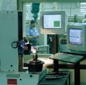
When a scheduled job at Waters Corp. is being set up to run on a CNC machine, all of the required electronic files can be downloaded from the shop's computer network. In Figure 1, for example, Deane Swanson can download the part program file, the single- piece setup file, the spindle probe file if needed, and file of tool offset data. These offsets, which are preformatted in this case for the Okuma control unit that they are headed for, are automatically applied to the NC program in the CNC. No offsets, or "tool comp data," are entered by hand.
In the meantime, the tool cart prepared for this job will be waiting. In the cart will be every cutting tool and tooling assembly, along with gages or accessories required for the job. The goal is to enable the operator to load tools into the tool changer, push the start button, and get a good part the first time, every time. There's no need to do test cuts.
Of course, the tool crib is keeping score. (See Figure 2.) And the tool crib has an enviable record here, too: For the first 11 months last year, when a cart of preset tools went to the shop floor, it was entirely free of reportable errors in 96.63 percent of the instances.
Mr. Berthiaume reports that by automatically downloading tool offsets rather than having operators enter them by hand, the shop saves an average of 50 hours per month. In addition, the errors from data input such as inverted numbers or misplaced decimal points have disappeared. Downtime due to an out-of-stock tooling item is almost zero across the shop. More important is the improved accuracy that all of the machines achieve because tooling and tool data are so precisely matched.
Getting to this point has not been an easy or quick effort. "If Waters Corporation is going to be a world-class manufacturer and a leader in its field, we had to follow this course," Mr. Berthiaume insists. "We had no other choice."
A Remarkable Company
Waters Corporation produces some of the most sophisticated fluid analysis equipment in the world. The company is a global leader in the design and manufacture of products for high-performance liquid chromatography, mass spectrometry and thermal analysis. This equipment is used to ensure the quality and consistency of chemical preparations, especially medicines, but also to analyze liquids in other laboratory applications.
In addition to leadership in instrumentation, the company is a leader in software development for chromatography. Waters offers the most widely used software for organizing, analyzing, reporting and storing the results of chromatography testing.
Founded in 1958 in Framingham, Massachusetts, the company spent its early years pioneering the science of liquid chromatography, a method by which substances in a liquid can be identified and quantified by allowing them to settle in an absorbent medium, such as silica, placed in a narrow column. It introduced the industry's first liquid chromatography system in 1963.
Waters moved to its current location in Milford, about 60 miles southwest of Boston, in 1973. Its headquarters and instrument manufacturing facility are located here. The manufacturing facility is ISO-9001 certified and registered with the U.S. Food and Drug Administration to produce Class I medical devices. About 1,000 people are employed in this facility, 137 in Machining Operations.
Because precision manufacturing is essential to the production of highly accurate, highly reliable instruments, the company has relied heavily on CNC machine tools. Presetting tools for these machines has been a standard procedure dating back to the opening of the Milford plant. Figure 3 shows some of the parts produced in the plant.
Presetting
Over the years, a rather sophisticated approach to tool presetting was developed in Waters' Machining Operations. The heart of this approach was a home-grown system for classifying tooling components and cataloging tooling assemblies. Using this software, the Production Engineering Department could put together a basic tool-preset sheet for the shop to follow.
Tool crib personnel used the tool-preset sheets to collect components from the tool crib, build the tool assembly, then measure critical dimensions on a tool presetter. Presetting ensures that these dimensions are within the tolerances set by the engineering department. The actual dimensions supplement the zero values used by the NC programmers when preparing NC part programs. The tool path is thus offset from the geometry to be machined to compensate for the length and/or diameter of the cutting tool, depending on the type of tool and the operation being performed. The CNC uses these values to recalculate axis motion while processing program commands.
If tools are not preset, it is necessary for the operator to install tools in the machine spindle and touch them off to determine their exact length and diameter, using the machine tool as a presetter. The dimensions then need to be transferred to the table of tooling values or entered by hand through a series of keypad strokes at the CNC control panel. Presetting saves the time-consuming touch-off steps and provides more accurate measurements because tool presetting equipment is especially designed for the precise measurement of tooling articles. However, the data entry step still creates the risk of human error and the possibility that workpieces will be machined inaccurately.
Although Waters' approach to presetting was conscientiously applied and well-disciplined, its limitations and shortcomings were a concern. "We had a tool catalog system but no method to actually manage our inventory within the tool crib or a process to download tool lengths directly to the machine tool," Mr. Berthiaume remarks.
About five years ago, the decision was made to move to a commercially available computerized tool management system for the tool crib and to purchase software for managing tool offset data for the presetters. "From the beginning of this initiative, we were determined that the inventory management software had to interface with the preset management software," recalls Mr. Berthiaume. "We also made it our ultimate goal to download offsets directly to the machine tools from the tool setters, and everything that preceded that step had to support that goal."
Waters sent a team to the International Manufacturing Technology Show (IMTS) in Chicago in 1994 to find and evaluate both types of software. That visit led the company to select two products that appeared to fit the need.
New Software In The Tool Crib
The software for inventory management in the tool crib was successful. However, implementing the new system proved to be a major undertaking. It took 18 months to complete, and it involved a team effort of the tool crib staff, manufacturing engineers and the information systems staff.
Waters had chosen PC-Toolcrib from SY-CON Systems, Inc. (Easton, Pennsylvania). Although later versions of this software are Windows-based, the version Waters implemented beginning late in 1994 was based on an upgrade of an MS-DOS format.
PC-Toolcrib is built around the concept that tools are an asset, not an overhead expense. Moreover, this asset should be managed as a source of vital manufacturing information, information that supports good decisions about operations and processes. This outlook was certainly compatible with Waters' policy of continuous improvement.
According to Mr. Berthiaume, implementing the new software taught Waters two important lessons. First, entering data is a big job, even when an existing tool catalog is well organized and comprehensive. Waters' tool crib staff eventually re-keyed all of its tooling data into a spreadsheet, item by item, to achieve a uniform tool description.
The second lesson learned is the enormous difference made by how the data is entered. Waters' existing tool catalog had more data elements than the version of PC-Toolcrib allowed for its database. This situation forced Waters to prioritize the information it could enter as data in the new system.
Top priority was establishing a consistent method for adding intelligence to the tool description and assigning a unique number. Using TOOL-Standards, a drill-down tool description generator in PC-Toolcrib, formats for describing 120 different types of tools were developed. Every format requires that tool diameter be entered first, followed by other characteristics such as flute length or style, depending on the type of tool. Additional codes may further classify the tool, but in all cases, the description must be sufficient to positively identify the tool. Consistent formatting of tool descriptions makes it easier to find a tool quickly and reduces the chances that the same tool might be entered under more than one description.
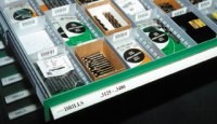
In the meantime, every compartment, bin or rack in every cabinet, drawer or storage unit was given a code so that the location of every tooling item could be identified and associated with the tools to be stored there (Figure 4).
The number of items on-hand at each location was entered, along with cost figures and other information—a tedious, necessary but one-time step.
While this PC-Toolcrib database was being developed, many of the reporting, tracking and accounting features of the system became operational. (See Figure 5.)
Presetter Software
At the same time Waters was implementing the tool crib inventory management software, it began implementing its new preset management software. This involved building a database of tooling assemblies and related measurement and dimensions, using another commercial software package to replace the home-grown system.
The plan was to interface this preset manager with the inventory management software to use the same database of tooling components. A tooling assembly, for example, could be represented as a list of the individual components compiled using the same descriptions used in the tool crib software. Completed assemblies would be given a unique number code and associated with the job number for which they were intended.
"Unfortunately, we couldn't get the systems to exchange data effectively," Mr. Berthiaume admits. "The tool crib software uses a relational database structure, whereas the presetter software was structured more like a word processing system. We naively accepted the assurances of the preset software vendor that the systems would be compatible, but I doubt they fully comprehended what we were trying to do." After 18 months of struggling, it became clear that the interfacing would be impossible to accomplish.
"By the summer of 1997, we decided to pursue a total solution to our preset management problem," Mr. Berthiaume explains. "We had seen the latest offerings in presetters at IMTS 96, including those from Zoller. We had had Zoller equipment in our shop since 1982, and were pleased with its performance, so we took another look at their software solutions."
At the time, Zoller was about to introduce its own preset management package. Although this software appeared to be what Waters was looking for, the company established two conditions on a decision to buy. Data from its current software had to be transferable to the Zoller software, and the Zoller software had to interface with the PC-Toolcrib software that managed the component inventory. Looking for a notable U.S. customer to showcase this new software, Christoph Zoller, president of Zoller Inc. (Ann Arbor, Michigan), agreed to these conditions. Late in 1997, Waters purchased two new Zoller presetters and Zoller's MVIS software system.
Meeting the conditions set forth was challenging. Waters had a catalog consisting of 4,000 tool assemblies for approximately 800 part numbers. Mr. Zoller agreed to modify his software to accommodate the needs and interests of Waters. Waters, in turn, also reformatted its database to facilitate data transfer, while SY-CON developed the software to integrate its tool crib database into the Zoller MVIS software.
Because of the size and complexity of this project, it took nine months to complete, which is many times longer than Mr. Zoller expects the typical presetter installation to take.
Advanced Presetters
The two new presetters represent today's generation of tool inspection technology. One is the manually operated "Premium" model, which Waters uses mainly for turning tools. The other is the CNC version, called the "Magnum," which Waters uses primarily for tools on machining centers. Both models have the same measuring range (up to 20 inches for length and 20 inches for diameter). Outwardly, the machines are identical except for two handwheels on the manual "Premium" model. Both models feature the same Windows-based graphic operating screen.
Both presetters take advantage of advanced digital image processing technology. The sensor carrier that travels up and down the column creates a beam of light that travels across the edge of the cutting tool and is detected by a dense array of photo diodes in the receiver. The profile of the tool prevents a part of the light beam from reaching the receiver. When activated by the light beam, the diodes in the receiver send signals to the processor, where the energized pixels are counted to derive a precise measurement of the tool's profile.
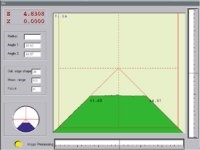
These counts can be used to calculate length, radius, runout, angle, and distance from edge to edge or point to point automatically (Figure 6). Unlike optical systems that rely on the operator to compare a magnified image against hash marks on a projection screen and make subjective judgements about the dimension indicated, digital image processing is objective and definitive. Digital imaging is therefore highly accurate and very repeatable. According to Mr. Zoller, these presetters have an accuracy of +1/-2µ (+0.00004/-0.00008 inch). Because measurements are in digital form, they can be recorded in a database and transmitted electronically.
To program the presetter, values for critical dimensions such as length, diameter, radius and so on, are entered from the engineering drawings. These drawings identify which dimensions are to be measured and give upper and lower tolerances for critical dimensions.
After a tooling assembly is clamped in the spindle, the CNC presetter automatically moves the image sensor carrier into place, finds the edges and focuses automatically, then takes measurements, rotating the tool to find, focus on, and measure other edges such as a second flute on a twist drill, if necessary. Measurements are recorded in a tool offset file unless they fall outside the limits, in which case the operator is alerted.
The manual presetter works in much the same way, except the operator uses the handwheels to position the carrier and focus the image. Manual operation, although slower than CNC, is more flexible. This flexibility is especially appropriate with turning tools because their dimensions and configurations are less predictable and more varied than milling tools. Measurements, however, are made automatically by the image processing system, using the same routines as that of the CNC model.
The presetters are interchangeable, Mr. Berthiaume points out. "We can measure any type of tool on either machine." He also points out that both machines are equipped with Zoller's optional top clamping mechanism, which was a strong selling point in favor of the Zoller equipment. This mechanism allows tapered toolholders to be clamped regardless of the style of drawbar stud on the holder. The shop has three styles of studs in use, but the presetters will accept any style without changeover.
After creating a file of measurements, the presetter software "post processes" the data for the machine tool on which the tools will be used. This step formats the data so that it can read by the machine tool's CNC and used to process machining commands. However, Waters worked with Zoller to create custom post processors allowing users to identify those assemblies for which certain offset values would be automatically supplied by the post processor, overriding the presetter measurement. For example, values for length and corner runout of a drill would be taken from the presetter, but the post processor would override the offset for diameter and enter zero, forcing the control to center the drill regardless of its actual diameter. These overrides help streamline procedures at the presetters.
The posted offset file is copied to the network file server, where it is stored in the folder for the particular part number it corresponds with.
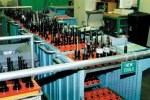
The tool crib assembles all of the tools needed for a job based on the production schedule. All of the tools and related items are in the cart and at the new tool waiting area (Figure 7) before the job is timed to hit production—but not too early. Because the presetter software and the tool crib inventory system are integrated, it is easy to track a tooling item on the shop floor.
One of the papers that goes out with the tools is a Preset Tool Exception Report that the operators fill out when a tool is incorrect or an offset value is in error. The same report notifies the crib if an item is missing and must be supplied to start the job run. These reports not only serve as a measure of the tool crib's presetter performance but also as a way to communicate constructive suggestions and comments, key elements in a culture of continuous improvement.
Record Of Success
With the presetter and the tool crib management systems in place, the results have been outstanding. According to Mr. Berthiaume, the company has reduced its perishable tooling expense in relation to standard dollars of output by almost 20 percent over the past three years.
Inventory of perishable tooling has been reduced by 20 percent over the same time period. Waters has identified inactive tools and removed them from inventory, consolidated similar items and sold some excess items.
The next step is to consolidate tooling assemblies and eliminate redundancies. Mr. Berthiaume expects this effort to reduce tooling inventory still further. Reducing the number of assemblies will make it easier to standardize on assembly configurations that have proven to be the most flexible, used the fewest parts, or were the most rigid.
In the meantime, the relentless drive to maintain the highest standards in tooling availability, error free delivery, and efficient operation will continue. For other shops that might be embarking on a journey toward the same goals, Mr. Berthiaume has these words of advice: "The rewards are great, but don't underestimate the scope of this undertaking. An organization that is truly progressive relies on vision and the ability to adapt. See what can be accomplished and give it your best shot. It can be done."
Related Content
Legacy After Loss: Writing the Next Chapter of a Family-Owned Machine Shop
When a beloved machinist’s passing left his shop in his children’s hands, the three siblings stepped up, transforming the business to honor his legacy and build a new future.
Read MoreAerospace Shop Thrives with Five-Axis, AI and a New ERP
Within three years, MSP Manufacturing has grown from only having three-axis mills to being five-axis capable with cobots, AI-powered programming and an overhauled ERP. What kind of benefits do these capabilities bring? Find out in our coverage of MSP Manufacturing.
Read MoreCan AI Replace Programmers? Writers Face a Similar Question
The answer is the same in both cases. Artificial intelligence performs sophisticated tasks, but falls short of delivering on the fullness of what the work entails.
Read MoreThe Power of Practical Demonstrations and Projects
Practical work has served Bridgerland Technical College both in preparing its current students for manufacturing jobs and in appealing to new generations of potential machinists.
Read MoreRead Next
Setting Tools Makes Small Shop Sense
Some people think tool presetting can be justified only in large operations. This Arizona shop shows how it makes sense almost anywhere.
Read MoreOEM Tour Video: Lean Manufacturing for Measurement and Metrology
How can a facility that requires manual work for some long-standing parts be made more efficient? Join us as we look inside The L. S. Starrett Company’s headquarters in Athol, Massachusetts, and see how this long-established OEM is updating its processes.
Read More






 (1).png;maxWidth=300;quality=90)


