Autodesk Fusion 360 adds PowerMill Technology and More
Sponsored ContentAutodesk’s Fusion 360 receives a major functionality upgrade with the addition of PowerMill, PowerShape and PowerInspect technology – offering more technology and better value.
Share
Fusion 360 with PowerMill offers more advanced manufacturing technology.
Software developer, Autodesk, recently announced significant changes that affect how customers can access its PowerMill, PowerShape, and PowerInspect manufacturing software tools. In this article we’ll dig into the changes to explain what’s happening and how they could impact you. Before we get into the details, let’s consider why Autodesk is making these changes now.
Put simply, Autodesk wants its customers to be able to access the best design & manufacturing technology that it can offer. By bringing PowerMill, PowerShape, and PowerInspect into the Fusion 360 family, users of these products will instantly benefit by being able to access new and emerging technology that helps manufacturers to make better parts more efficiently.
View Fusion 360 OverviewFusion 360 - now with added Power
So, what’s changing?
In short, PowerMill, PowerShape, and PowerInspect are becoming part of the Fusion 360 family of products. As an example, where previously you might have subscribed to PowerMill, you’ll now be able to subscribe to Fusion 360 with PowerMill. At first glance, this might feel like a simple change of name. In reality, the changes go much further. These new offerings include additional technology such as Fusion 360, Fusion 360 Team, and access to a number of “extensions” inside Fusion 360. These extensions unlock the most advanced manufacturing tools offered by Autodesk today, while also paving the way to access next generation workflows in future.
The new Fusion 360 with PowerMill Ultimate offering is now the same price as the previous PowerMill Premium version yet contains additional advanced functionality for high-end machining. Check out this example of hybrid manufacturing capabilities using Fusion 360 with PowerMill.
Hybrid manufacturing of Inconel parts using Fusion 360 with PowerMill
For a more detailed look at the changes, you can read the official Autodesk blog.
Fusion 360 with PowerMill
How do these new offerings stack up? What technology do they provide, and how can this help you in your typical working day?
Overview of Fusion 360 with PowerMill
We’ll start off with a simple example. In this case, we’ll consider a job shop looking to CNC machine parts supplied by their end customer. The manufacturer didn’t design the part but is responsible for designing and making fixturing to allow the finished parts to be made.
“We use PowerMill to make edits to our NC programs on the fly – it is truly without walls. Fusion 360 is the fastest software we’ve ever used to get steel cutting”
Anthony Wooten
Precise Tooling Solutions, Columbus, IN
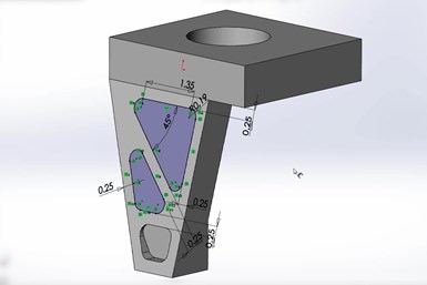
3D model shown in original CAD system (not Fusion 360).
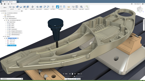
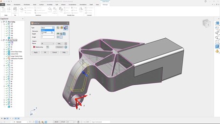
We start off by opening the native 3D CAD model inside Fusion 360 using AnyCAD. As the name suggests, AnyCAD allows practically all CAD model formats to be opened without the need for any conversion (meaning there’s no loss of data). Once imported, Fusion 360 modeling tools can be employed to make a variety of changes and additions to the model in readiness for manufacture to begin.
In this example, there is a need to design a fixture to secure the part during CNC machining. This is easily achieved using the parametric and assembly modeling capabilities within Fusion 360. The necessary plates, clamps and other components are quickly extracted from a user-defined library of parts and assembled to produce the finished fixture. At this point, the finished component and fixture assembly would typically be passed to a different member of the team for CAM programming – in this case using PowerMill.
Fixture designed using Fusion 360.
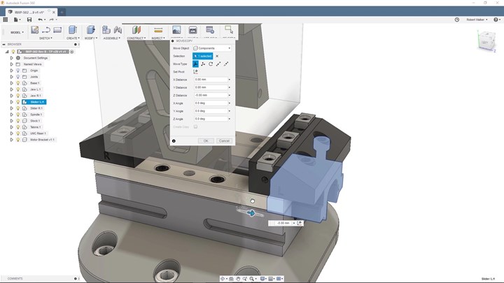
This relatively simple part requires the use of 3+2 (or positional 5-axis) machining to produce the main 3D form plus the various holes and pockets. Once the toolpaths have been created, it is commonplace for them to be simulated to check for collisions or near misses, confirm that the CNC programs remain within the machine’s travel limits, and identify any erratic motion that could compromise the surface finish of the machined part. On this occasion, the simulation reveals a collision involving the tool assembly and rotary table of the machine.

Simulation inside PowerMill reveals collisions between table and spindle.
While the solution may initially seem simple, it’s surprisingly easy for teams to fail to communicate effectively, resulting in delays and costly mistakes being made. It’s here that the collaborative capabilities of Fusion 360 Team play a role. The PowerMill CAM programmer can create annotated views that show the problem. These can be shared with the relevant stakeholders using Fusion 360 Team.
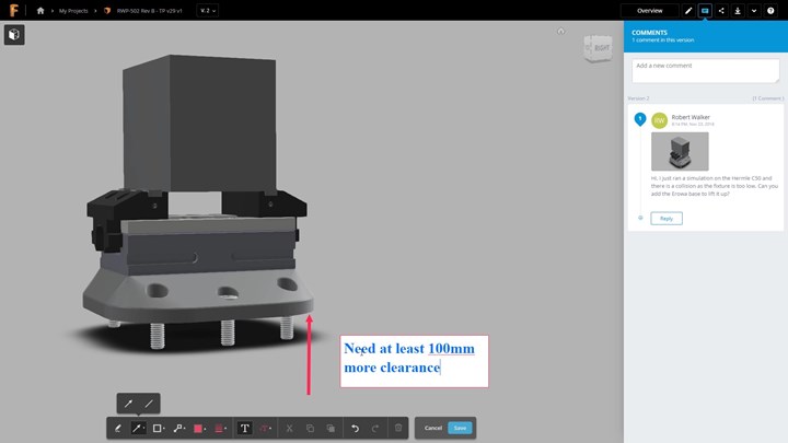
Teams can collaborate on mobile devices to make decisions quickly.
As Fusion 360 – Team can be accessed on mobile devices, the stakeholders are notified immediately – allowing them to react quickly – even if they’re not at their desks. This allows important decisions to be made quickly – avoiding additional delays that could impact production schedules. In this case, the chosen solution is to incorporate a riser plate into the fixture that lifts the part away from the table. Back in PowerMill the CAD model is updated and the toolpaths re-simulated to confirm that the collisions are no longer present.
The one true constant - change
A common problem that affects many contract manufacturers and job shops is last-minute design revisions from the end customer. By definition, the lateness of these changes puts the manufacturer under immense stress. This can lead to procedural corners being cut which can increase the chances of costly mistakes being made.
However, the AnyCAD capabilities within Fusion 360 can help here too. As Fusion 360 is effectively displaying the native CAD file, when changes are made, Fusion 360 instantly knows and can inform the users allowing them to decide how best to proceed. The associativity in Fusion 360 goes further and allows the changes to be pushed through the rest of the manufacturing model (e.g. updating a fixture to adjust to the new design it’s supposed to hold) to minimize the amount of manual re-modeling work that will be needed.
Once the CAD model is updated fully, the choice is whether to use Fusion 360 CAM programing tools or to return to PowerMill to access more advanced 5-axis capabilities.
The new Fusion 360 with PowerMill offering comes in two versions – “Fusion 360 with PowerMill Standard” and “Fusion 360 with PowerMill Ultimate”. The version you choose depends on your specific application and CNC machinery. If you own 3-axis CNC equipment, you’ll almost certainly be using the “Standard” version, whereas if you’re driving 5-axis machines, industrial robots, or wanting to create NC code for machining more advanced geometry (like blades, blisks/IBR rotors, ports and manifolds) you’ll probably be best off going for the “Ultimate” version. For more information on the specific differences between the two versions, check out the official Autodesk blog.
Fusion 360 with PowerShape
Those already using PowerShape will be familiar with its range of modeling for manufacture tools. Now the combination of Fusion 360 with PowerShape expands the overall design capabilities of the application.
3D CAD model shown in PowerShape.
In this workflow example we’ll consider the design and manufacture of a prismatic aerospace bracket and see how Fusion 360 with PowerShape provides technology to help validate part performance during the early design phase of a project and help avoid waste during subsequent manufacturing.
Fusion 360 provides a range of mechanical and thermal simulation tools that can be used to check how a part will cope with the stresses and strains expected during its life in service. Simulation studies can be used to analyze static and non-linear static stress, as well as to identify modal frequencies and buckling modes.
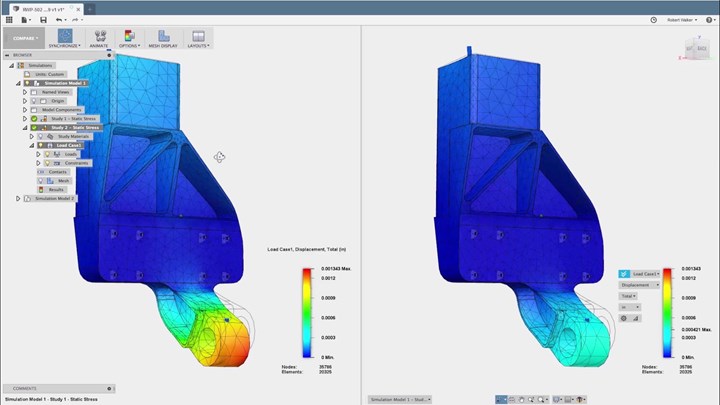
Mechanical linear stress analysis compares part performance when using aluminum (left) and mild steel (right) for displacement.
Studies can also be used to compare the performance of different materials. In this example, aluminum and mild steel are compared to determine the likely displacement under the expected load in service and identify potential failure modes.
“We use PowerShape to design electrodes. The electrode design was key to be able to take the file, design it, move it to PowerMill and auto generate a toolpath – it’s 100% human error free.”
Anthony Wooten
Precise Tooling Solutions, Columbus, IN
As these studies require significant computing power, Fusion 360 can carry out the studies using the cloud, allowing simulation results to be calculated faster, while freeing up desktop computers for other tasks. Simulations can also reduce the need to produce physical prototypes, allowing problems to be identified early and design changes to be made, all of which saves time and resources, and allows part manufacture to start earlier.
Autodesk has already repackaged its FeatureCAM product under Fusion 360, and this latest development sees even more of its advanced manufacturing products joining the Fusion 360 family. These changes simplify the choices offered by Autodesk, yet provide manufacturers with access to next generation technology to make it easier for companies to maximize productivity and grow their business in the future.
For more information on the range of Autodesk advanced manufacturing software visit www.autodesk.com/make.