CAM software strategies that define how a tool moves through a part can have a profound impact on machining efficiency. By themselves, however, even the most advanced tool paths don’t account for some of the unique circumstances that dictate how machinists cut parts in real-world manufacturing situations.
That said, why should the role of CAM software stop with the tool path? What if the software could not only generate an effective strategy for tool motion, but also intelligently apply that strategy according to application-specific variables? That’s precisely the idea behind iMachining CAM software from SolidCAM (Washington Crossing, Pennsylvania).
Many of the software’s purported benefits—primarily deeper, faster and more efficient cutting with less wear and tear on tools and machines—result from a toolpath strategy designed to keep the mechanical and thermal load on the cutter constant. However, what truly sets the system apart is a proprietary algorithm that automatically determines feeds, speeds, stepovers and cutting depths for a given job based on attributes specific to the machine, cutting tool and workpiece, says Chris Calderone, iMachining product manager. This reduces programming time and eliminates the typical trial-and-error approach to optimizing cutting parameters, not to mention the broken tools and scrapped parts that can entail. Moreover, the software enables users to quickly and easily adjust those parameters to machine more cautiously or aggressively depending on the particulars of their situation.
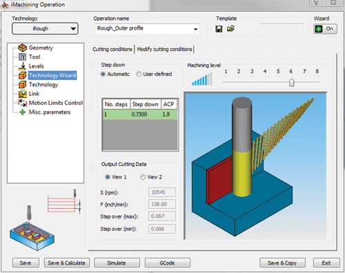
Mr. Calderone contends that this approach to determining parameters is more sophisticated than pulling recommended speeds and feeds from an Excel spreadsheet or similar database. Rather, iMachining relies on the user to define the specific machine, cutting tool and workpiece material for a particular job via an interface known as the “Technology Wizard.” This requires entering relatively few key attributes—a machine’s horsepower, rigidity and maximum feed and speed, for example—and the software uses information from tool and material libraries to avoid duplicate data entry, Mr. Calderone says. The user then adjusts a slider to determine how aggressively to machine on a scale of 1 to 8. The algorithm takes all of that input into account to determine feeds, speeds and stepovers. If one variable changes, the others adjust automatically to stay in sync without pushing the equipment beyond its limitations. For example, if the user selects a shallower cutting depth to machine a part in two passes instead of one, feeds, speeds and stepover will increase accordingly.
The ability to adjust cutting aggressiveness on a sliding scale is especially valuable because ideal cutting parameters vary from job to job, says Anthony Calderone, chief technical officer at SolidCAM. For example, he says, consider an application with less-than-rigid fixtures, or a scenario in which a shop on a tight delivery deadline must preserve its few remaining cutting tools to complete a part run. In such cases, shops are likely to start reducing speeds and feeds, whether through the program or at the machine. Simply adjusting the slider and letting iMachining determine cutting parameters enables users to forgo that potentially time-consuming and error-prone process, Mr. Calderone says. “We knew that people did this sort of thing all the time, and we wanted to build it into the system,” he explains.
This “intelligent” approach also extends to the tool path itself, Mr. Calderone says. Plotting tool motion in a way that avoids variations in tool load is nothing new. However, iMachining takes workpiece geometry into account when plotting this motion. The result is a path that keeps the tool engaged in the cut and avoids air cutting and repositioning moves that can stress the cutter and add time to the process, he says.
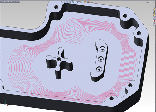
SolidCAM refers to this tool path as a “morphing spiral.” As that name implies, the path proceeds in a looping motion that keeps the tool engaged while avoiding sudden changes in direction. However, only the interior of the spiral is circular. The outer portion conforms to the geometry of the workpiece feature being machined. As machining proceeds, the path “morphs” from the geometric contour to a pure circle or vise versa depending on whether the cut begins at the outer or inner portion of the spiral. When the area to be machined is impossible to cut with a single spiral, the software automatically sub-divides that portion of the geometry and separates channels and tight corners. Each sub-area can then be cut with its own spiral.
To accomplish this morphing, the software adjusts stepover at various points in the tool path—larger stepovers at thicker points along the spiral, smaller stepovers at thinner points, never exceeding maximum and minimum values specified by the user, Mr. Calderone says. The software also uses stepover adjustments to keep an equal portion of the cutter engaged in the material at all points in the tool path. This maintains a consistent tool load. When these goals contradict each other—for example, when thinner areas of the spiral’s contour call for a lower stepover value that would otherwise cause a sudden decrease in tool load—the software adjusts feed rates to compensate. (Click the link under "Editor's Picks" in the upper right of this screen to see video of a spiral morphing tool path.)
Chris Calderone stresses that far from being limited to 2 1/2-D pocketing, these tool paths can be applied in virtually any machining situation (see "Editor's Picks" in the upper right of this screen for a link to a video demonstrating an iMachining tool path applied on a mill-turn application). The morphing spiral approach is also equally effective in roughing, semi-finishing and finishing operations. However, iMachining’s greatest benefit is the time and cost savings of applying that strategy in a way that meets specific goals particular to specific applications, Mr. Calderone says. “Yes, there is a tool path at the heart of it, but the big difference with iMachining is that it just works, regardless of what the variables are,” he concludes.