
Choose the Correct ID/OD Gage for the Task
Benchtop and portable comparator gages each have their place, but the differences are more than surface deep.


Circles are a frequently produced form in the shop. Many different processes generate this form — including turning, milling, centerless grinding, boring, reaming and drilling — and there are a variety of gaging methods used to measure inside and outside diameters (ID/ODs) of these circles. For simple operations, shop employees can measure a hole with a scale or a fixed go/no-go gage. For more complex operations, employees can use precision measuring machines like coordinate measuring machines (CMMs) and optical or vision machines. However, in production environments, employees can accurately measure most ID/ODs using one of several varieties of comparator gage.
Comparator gages for ID/OD come in two basic styles: benchtop and portable. Operators with shopfloor level skills should use these gages in high-volume, high-performance applications. Because these gages provide a comparative measurement, they require a master to set the zero reference point when determining part deviation. Comparator gages have limited travel, but this allows the use of a high resolution dial or digital indicators and high resolution electronic probes with amplifier readouts.


Choosing whether to use a benchtop or portable gage will depend on the size of the part being measured and whether the user will bring the part to the gage or the gage to the part. Typically, benchtop comparative gages work best for small parts and are generally restricted to measuring single dimensions or features that are less than 255 millimeters (~9 inches) in diameter and not more than 25 millimeters (~1 inch) deep. Portable ID/OD gages can go as large as 2,500 millimeters (~8 feet) and as deep as 125 millimeters (~5 inches). If a manufacturer needs to go deeper than that, bore or plug gages are a better choice.
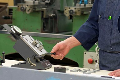
What Should You Know About Benchtop Gages?
Benchtop gages are capable of higher precision than portable gages, with resolutions of 0.0005 millimeter (0.00002 inch) readily achievable. Typical of these are the “plate gages” seen in the bearing industry or anywhere that requires fast readings of ODs or IDs. The tilting stage plates are used to set and locate the part each part and this basic design has been around for more than 50 years. Plate gages are convenient for fast, comparative gaging of flat, thin-walled parts, such as bearing rings. In these applications, users must make diameter measurements in a plane parallel to at least one of the faces, and sometimes at a particular depth on the ID or OD. Versions are available for 2-point or 3-point measuring that allow for the checking of parts that have form errors with even or odd numbers of lobes.
What Should You Know About Portable Gages?
If the part is large or awkward to manipulate, or if measurement requires setting it up on a machine, use a portable, beam-type gage. Beam-type gages are available with maximum capacities from 25 mm (~1 inch), to about 1100 mm (~40 inches), the largest ones being used to measure bearings and large bores in casting. Actual measuring range is typically 10 mm (~0.4 inch), but is ultimately determined by the indicator installed.
Most portable ID/OD gages lack centralizing stops and require “rocking” like a bore gage to find the true diameter. When rocking the gage, use the fixed contact as the pivot and allow the sensitive contact to sweep across the part. Likewise, if the gage must bear its own weight against the part, make sure the fixed contact bears that weight, not the sensitive one.
Do not expect high precision readings with a portable gauge when measuring dimensions of a foot or more. Most indicators on these large-capacity gages will have minimum grads of 0.01 millimeter (or 0.0005 inch). This is adequate, given the inability of most machine tools to hold tolerances much tighter than about 0.05 millimeter (or 0.002 inch), for parts that large. Beware of the gage claiming to measure more than 900-millimeter (or 3-foot) ID/OD capacity with 0.001-millimeter (or 0.00005-inch) resolution — the gauge is probably not capable of repeatable measurements.
To accelerate and potentially improve the gaging process with portable gages, users can replace mechanical dial indicators with a digital indicator that has dynamic capabilities. This enables the gage to capture minimum or maximum readings or calculate the difference between the two. This also frees operators from having to carefully monitor the motion of a rapidly swinging needle on a dial indicator when rocking a portable gage or checking for deviation on a benchtop version.


Related Content

How to Calibrate Gages and Certify Calibration Programs
Tips for establishing and maintaining a regular gage calibration program.
Read More
A Case for Combining Workholding with Optical Scanning
Automotive dies and die inserts are often complex, one-off parts with little room for error. Integrity Tool's investments in modular workholding tools and 3D optical scanning have allowed the company to create niche capabilities for its CNC machined parts.
Read More
5 Things CNC Operators Must Know About Sizing Adjustments
For CNC operators, sizing adjustment is an essential skill. Keep these points in mind when training new CNC users.
Read More
Choosing the Correct Gage Type for Groove Inspection
Grooves play a critical functional role for seal rings and retainer rings, so good gaging practices are a must.
Read MoreRead Next

Automating the Indicator Calibration Process
Eliminate human error when calibrating precision hand tools by leveraging modern vision systems.
Read More
When to Use 2D or 3D Surface Measurement
Instead of committing exclusively to 2D or 3D surface measurement, shops should consider their use cases.
Read More
Tips for Choosing Filter Settings When Measuring Round Shapes
When interpreting measurement data, the correct filter setting is necessary to see the difference between surface roughness and part roundness.
Read More