
Designing a 3D Printed Part with Machining in Mind
Designing extra stock and mounting features into a 3D printed part can aid in machining processes downstream.


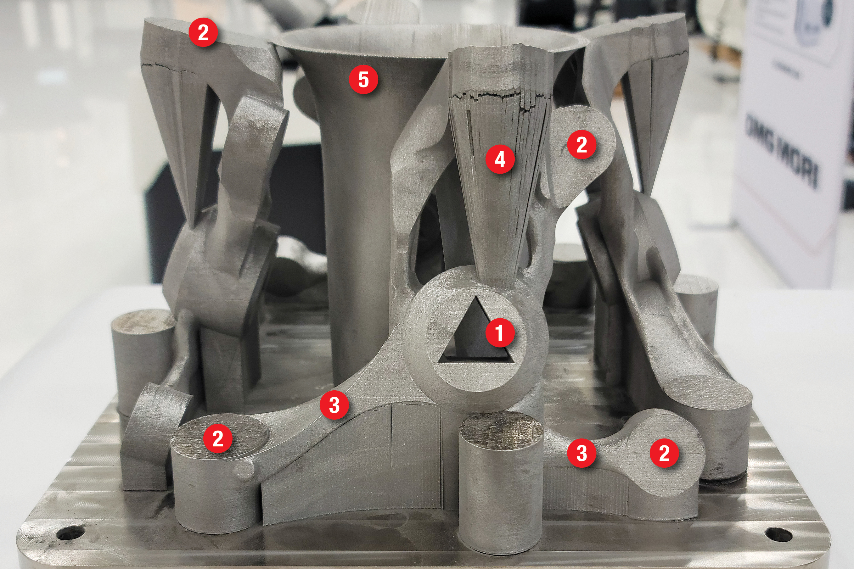
Photo Credit: Siemens Industry Inc.
Machining can be an obstacle in the quest for “first-time right” 3D printing — designers need to ensure parts can be held in the machine tool, and that machines can access the features and critical surfaces that need to be machined. The digital thread can aid in this by connecting designers with machining simulations, so they can adjust the part accordingly.
Adam Hiller, additive manufacturing and Siemens Xcelerator portfolio solutions consultant at Siemens Digital Industries Software, designed this 3D printed steering knuckle for an eRod (electric dune buggy) from Kyburz using Siemens software solutions connected by the digital thread. “We’re thinking of the entire lifecycle now instead of just saying, ‘Oh, the part looks cool, it does what we want and it will satisfy all our criteria,’” he explains. “We're saying, ‘Let's also make sure that everybody else downstream is able to do as automated of a process as possible.’” Here are several features on the as-printed part that were designed with machining in mind:
- Triangular mounting feature in center spindle hole. This triangle within what eventually became the spindle hole served as a mounting feature, and was eventually milled out.
- Extra stock in bolt holes. The four bolt holes were also machined (instead of printed) to ensure quality and precision at the points where the part attaches to the vehicle.
- Extra stock on critical surfaces. Designers added extra stock to the sections of the part that make contact with the vehicle. These areas were machined to ensure a flush fit.
- Machinable support structures. Support structures in metal 3D printed parts serve the important functions of holding up overhanging features and distributing heat away from the part to prevent warpage. Once the part is out of the printer and support structures are no longer necessary, they are typically removed by hand or machine tool. Hiller wanted postprocessing for the steering knuckles to be as automated as possible, so he ensured that the machine tool could access all of the support structures for removal.
- Trumpet mounting feature. While simulating the machining process, machinists realized the parts were at risk of being ripped off the build plate due to vibration. Hiller worked with the machinists to create a trumpet-shaped structure in the middle of the build plate to securely mount the parts for machining.
To learn more about how Hiller and his team used the digital thread in this application, read “Digital Thread Enables First-Time Right 3D Printing.”
Related Content
-
Digital Thread Enables First-Time-Right 3D Printing
Connecting all stages of manufacturing, from design to postprocessing, helps break down barriers to industrializing additive manufacturing.
-
4 Ways 3D Printing Is Changing Medical Implants
Additive manufacturing provides new ways of making medical implants, but its impact is greater than this. How 3D printing is changing medical manufacturing and improving patient outcomes.
-
An Additive Manufacturing Machine Shop
Finish machining additively manufactured implants requires different pacing and workflow than cutting parts from stock — different enough for an experienced manufacturer to warrant a dedicated machine shop.


