
Determining Out-of-Roundness at the Point of Manufacture
George Schuetz, Mahr Inc.’s Director of Precision Gages, offers these techniques for measuring roundness on the shop floor.

Share


Roundness, like many other geometric terms, has a very clear definition within ISO and ANSI/ASME form standard documents. Errors of form normally come from the manufacturing process when components are laid upon the part. The linear components are the surface finish while the circular errors are defined as the roundness errors.
Circular geometry gages, with their precision spindles, are the best — and the standard — method for measuring out-of-roundness. While great strides have been made in speeding up the roundness measuring process, and these machines are getting more cost-effective, they are usually confined to applications where a very high degree of accuracy is required concerning part geometry.


For many parts, however, it just may be too time-consuming to do a full roundness trace on a form machine and most likely many of these jobs may not require it. While a true roundness measurement requires a complex description of the geometric and dimensional relationships of dozens or hundreds of points on a diameter, most job specifications simply call for parts to be "round within 0.XXX mm variation in radius." In other words, as long as no point on the radius falls outside of two concentric circles, the actual shape of the surface is secondary.
Now that we understand this, there are ways to approach roundness measurement that can provide a practical, low-cost alternative to a circular geometry gage. Although these methods rarely give a technically accurate measurement of roundness, they are often “close enough” to give a good indication of the functional implications of an out-of-round condition. Typically, if a part can pass this practical test which includes many other measurement and gage considerations, then it is apt to pass the roundness parameter. If you understand the nature of out-of-roundness, it may be possible to qualify the part using conventional equipment such as a micrometer, bore gage, comparator stand or a V-block arrangement.
Knowing a little about the geometry involved is the key. Typically, out-of-roundness is either symmetrical, involving regular or geometrically arranged lobes or points on the part's circumference, or asymmetrical, where the lobing is not regular. Most machining processes create symmetrical lobing, producing either an even or an odd number of lobes. Even-number lobing is sometimes seen in precision boring operations, caused by a worn or out-of-balance spindle. Odd-number lobing may be caused by a 3-jaw chuck (producing a 3-lobed workpiece), or a centerless grinder (which may create a 5-lobed condition). Asymmetrical lobing cannot be measured by the means described here. It is evidenced by irregular travel of an indicator and is usually indicative of a problem in the tool.

The characteristic for even-number lobing is that each lobe is opposed by one diametrically opposite (see Figure 1). The piece, therefore, will have major and minor diameters. Knowing this, we can gage the part using simple two-point, or diametrical measurement methods. The difference in the differential measurements will generally be twice the out-of-round value due to the diametral versus radial method of assessment. For example, if the specs call for a part that is "round within 0.005 micron variation in radius," we can measure using a simple comparator, and reject any part where the Total Indicator Reading (TIR) is larger than 0.01 micron.
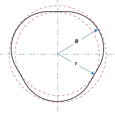
Parts with an odd number of lobes present a more complicated problem. As shown in Figure 2a, where an odd number of lobes exist, each lobe is diametrically opposed by a flat area. These parts can be measured on a V-block fixture, using the following formulae to establish the included angle of the V-block, and the multiplication factor (illustrated in Figure 2b):
1) Included angle:
2ø = 180 - 360/n
Where "ø" equals half the included V-block angle, and "n" equals the number of lobes.
2) Multiplication Factor:
M = (R + R csc ø) - (r + r csc ø)
or
M = (R - r) (1 + csc ø)
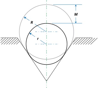
Where "M" equals the measured difference (as shown on the indicator), "R" equals the radius of the circumscribed circle, "r" equals the radius of the inscribed circle, "ø" equals 1/2 the included angle of the V-block, and "R - r" equals the specified radial variation (tolerance) for the part.
This can be simplified. The table below, worked out from these formulae, gives the required multiplication factor and included V-block angle for 3-, 5-, and 7-lobed conditions, which represent the majority of the odd-lobed conditions found in normal machining practice.
Condition Multiplication Included
Factor V-Block Angle
Three lobes 3.00 60⁰
Five lobes 2.24 108⁰
Seven lobes 2.11 128⁰34'
Let's use a specific example. The part is specified to be "round within 0.0001 in. variation in radius." We know the part was produced on a CNC lathe using a 3-jaw chuck, and we have previously determined (possibly through the use of a circular geometry gage on a short-term basis) that the process generates a 3-lobed condition. Therefore, we use a gage having a V-block fixture set up with a 60-degree included angle. To determine allowable variation in radial out-of-roundness, multiply 0.0001 in. x 3. Any TIR larger than 0.0003 in. is out of tolerance.
Keeping in mind that such measures are only approximate, these techniques provide a good, practical means to determine out-of-roundness on the shop floor right at the point of manufacture.


.png;maxWidth=300;quality=90;format=webp)
Related Content

The Many Ways of Measuring Thickness
While it may seem to be a straightforward check, there are many approaches to measuring thickness that are determined by the requirements of the part.
Read More
Using Air to Measure Squareness
Though most frequently used for diameter measurements, an air plug and platen can be readily configured to measure perpendicularity.
Read More
Machined Part Geometry Measurement
Uncertain about uncertainty? Having trouble remembering the difference between accuracy and precision? Read on to review key metrology terms relevant to the ISO Guide to the Expression of Uncertainty in Measurement (ISO GUM).
Read More
A 100-Year-Old Measurement Tool That is Still Used Today
The reed mechanism was a breakthrough in high-precision measurement and is still used today for sub-micron or even nanometer resolution applications.
Read MoreRead Next

OEM Tour Video: Lean Manufacturing for Measurement and Metrology
How can a facility that requires manual work for some long-standing parts be made more efficient? Join us as we look inside The L. S. Starrett Company’s headquarters in Athol, Massachusetts, and see how this long-established OEM is updating its processes.
Read More