
Five-Axis Software Drives Four-Axis Machining Gains
Using five-axis CAM software to program rotary fourth-axis operations has simplified the machining of this company’s most complex parts, improved flexibility and enabled faster, more accurate programming.
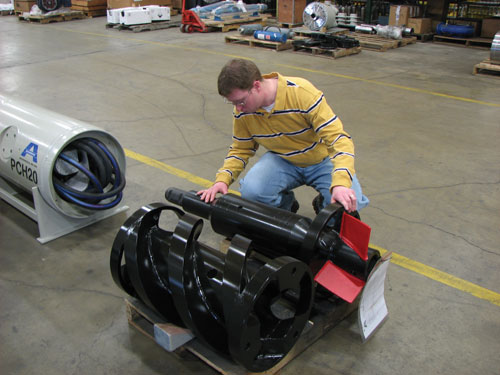
Design engineer Nathan Lindeman makes a final inspection of the swivel assembly of a guided boring machine. In the foreground is the auger weldment incorporating an end cap produced via four-axis machining and an auger flighting produced via Y-offset, four-axis machining.
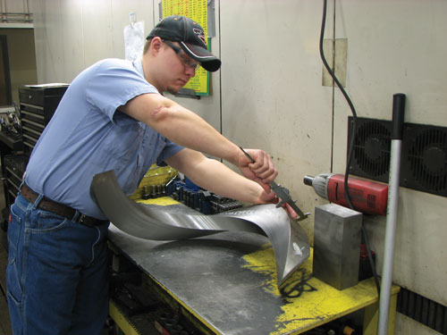
Machinist Tim Staver checks the cross section of an auger flighting. This part is machined with the cutting tool offset from the radial center to achieve a right-angle cross section, as opposed to the keystone shape that would result from on-center machining.
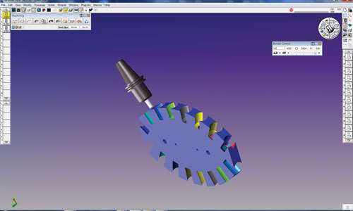
This screenshot from GibbsCAM’s Cut Part Rendering (Flash CPR) toolpath verification feature depicts the machining of two bearing cage sections. The machine’s fourth rotary axis enables machining the bearing cavities on both edges of the workpiece in one setup. As shown here, users can direct the software to display each operation in a different color.
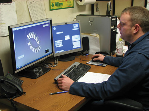
Aron Bishop programs a bearing cage section with GibbsCAM five-axis to machine two pieces per blank with four-axis rotary machining. Different sizes of bearing cages are laid end-to-end to create entire bearings from 20 to 44 inches in diameter.
Share


Shops don’t necessarily need five-axis machine tools to take advantage of five-axis programming strategies. Consider the experience of tunneling equipment manufacturer Akkerman Inc., a shop that uses five-axis CAM software to great effect for programming rotary fourth-axis machining operations. In fact, the company credits that software, GibbsCAM from Gibbs and Associates (Moorpark, California), for boosting flexibility, simplifying the machining of its most complex parts and reducing programming time.
Founded in 1973 and now in its second generation of family ownership, Akkerman Inc. operates out of a 60,000-square-foot facility on Akkerman family land in rural Minnesota, about 85 miles south of Minneapolis-Saint Paul. There, 77 people work two shifts to produce pipe jacking equipment, earth pressure balance equipment, and trenchless tunneling machines that bore holes as large as 14 feet in diameter that range from dozens of feet to several miles long.


Nearly every machine produced at Akkerman is a custom build. In addition, the company constantly works to improve product designs to accommodate particular earth conditions, customer preferences, pipe diameters and other considerations, explains Terry Lewis, manufacturing engineer. This results in frequent changes to parts and assemblies. On the shop floor, CNC programmer Aron Bishop is responsible for making those changes happen, Mr. Lewis says.
For Mr. Bishop, supporting and keeping up with engineering and product development often involves writing as many as four or five new programs every day. GibbsCAM software, which the company purchased three years ago, “saves me a lot of time,” he says. To illustrate these time savings, he describes the process for making bearing cages that space the radial and thrust roller bearings in the company’s powered cutter heads. Ranging from 20 to 44 inches in diameter, the cages are assembled by laying as many as a dozen 10- to 11-inch-long radial sections end-to-end. The sections were difficult to visualize and program manually because they require a great deal of point-to-point motion, especially for Z-ramp contouring on the bearing diameter, Mr. Bishop says. In fact, manually programming his first bearing cage took two days, with a good portion of that time spent calculating radii angles and locations.
Now, Mr. Bishop can program a new bearing cage in little more than an hour. Models are supplied in SAT format from IronCAD and read directly into GibbsCAM. From that point, he can use the CAM software to modify the models, fix geometry and move holes and other features. The model also provides all angles and locations, eliminating much of the manual work Mr. Bishop previously had to perform. “I don’t need to know any of that,” he says. “I just click on a surface to machine, align my Cartesian coordinate system, select the geometry, click ‘do it’ and GibbsCAM generates the tool path. It computes all the data from my geometry and coordinate system instantly.”
More recently added functionality compounds the benefits of the software’s time savings and ease of use. Investing in GibbsCAM’s five-axis module to program a fourth, rotary machine tool axis has facilitated a more flexible approach to programming and manufacturing many of the company’s most complex parts, Mr. Bishop says. As a result, the company has realized faster, more accurate programming, simplified or eliminated operations on complex parts, and reduced assembly work, among other advantages.
The machining of the bearing cage provides one example of how the company uses this capability. With the rotary fourth axis, two bearing cage sections can be machined in a single setup from a single, flat block of ductile iron. First, both sides of the block are faced. Then, profiling proceeds on the two outer edges to create radii that will eventually form part of the bearing cage OD. The stock is then moved to the rotary fourth axis. There, all bearing seats on one radius are bored before the part rotates 180 degrees for boring on the other radius. Finally, the workpiece is laid flat on the table for milling operations that create the ID portions of the two segments and separate them from the original block of material.
In some cases, using the five-axis CAM system to program the rotary fourth axis does more than just simplify production of complex components. In fact, some parts would be impossible to machine without it. For example, Akkerman recently developed a new cutter head with an integral swivel for its tunneling machines. The shop ran into trouble in its first attempts to machine a complex, helical flighting for the cutting head’s auger. “It was Aron Bishop who made it happen, using the rotary fourth axis programmed with GibbsCAM five-axis,” Mr. Lewis says. “Without that combination, we would not have been able to make the part.”
The helical flighting begins as a 5,500-pound cylinder measuring 31 inches long and 16 inches in diameter with a wall thickness of approximately 5 inches. First, the ID and OD are turned in a lathe. Then, a machining center cuts five helical grooves through the cylinder’s wall. At this point, the cylinder essentially consists of six separate helices attached at the ends. Subsequent sawing separates the pieces, three of which are welded to end plates and a central cylinder to form the auger.
Mr. Bishop programmed the first part manually. At that point, the shop had not yet invested in five-axis programming, but it was using the rotary fourth axis for the helical cuts. During that operation, he discovered a problem. “Cutting on center resulted in a cross section that was narrower toward the center. It was like a pie segment, not the rectangular cross section that the part required,” he explains. “I knew we would need to cut along the Y axis, but off center.”
That was when Akkerman added the five-axis option to GibbsCAM. This would enable the company to program four-axis work, offset in the Y axis and provide full control to the tool axis for parts with sufficient complexity to warrant surface milling strategies or where surface contouring is desirable. With the ability to offset in the Y axis, the shop could successfully machine the auger flighting with the proper cross section.
The five-axis module also helped with contour machining for other components for the swiveling head. As an example, Mr Bishop cites the plates that attach to the ends of the auger flighting, where soil pushes into the auger. “The three openings on the plates are cut at angles to match the flighting, and I had been milling them with simple surface machining. Using the five-axis module made it easier, and using five-axis milling strategies results in a much smoother, cleaner surface.”
Mr. Bishop foresees much more component combination and simplification in the future. One next step might be obtaining a rotary attachment that is sufficiently rigid for extra-heavy work on the shop’s Kitamura Bridge Center 10. This would enable machining the auger as a single piece, rather than as a weldment consisting of a cylindrical shaft, three helical sections and two end plates. “Additionally, the Kitamura allows me to use the GibbsCAM postprocessor to save a lot more setup time because we can rotate the coordinate system in combination with a touch probe, which is especially useful for heavy work,” he adds.


Related Content

SolidCAM iMachining and Technology Wizard: Faster Machining and Longer Tool Life
Smarter toolpaths to tackle modern machining challenges.
Read More
The Smarter Way to Take Full Control of Your CNC Machine Shop
Designed to bridge the gap between CAM programmers and shop floor operators, SolidShop provides a seamless, real-time solution for managing G-code, tracking production and eliminating costly mistakes.
Read More
Five-Axis CAM Strategies Cut Cycle Time for Two Shops
After being acquired by the same parent company, two shops found that working together and sharing knowledge improved both of their bottom lines.
Read More
The Power of Practical Demonstrations and Projects
Practical work has served Bridgerland Technical College both in preparing its current students for manufacturing jobs and in appealing to new generations of potential machinists.
Read MoreRead Next

OEM Tour Video: Lean Manufacturing for Measurement and Metrology
How can a facility that requires manual work for some long-standing parts be made more efficient? Join us as we look inside The L. S. Starrett Company’s headquarters in Athol, Massachusetts, and see how this long-established OEM is updating its processes.
Read More