
Inspection With X-Ray Vision
Could detecting and quantifying the internal flaws of complex parts be as easy as operating a microwave oven? Kevin Legacy, manager of computed tomography (CT) and engineering at Carl Zeiss IMT Corporation, thinks so. He compares the manufacturer's Actis line of industrial CT systems to the one-button operation of the kitchen appliance.
Share


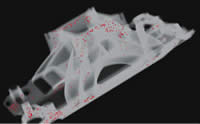
CT can be implemented to examine delaminations in bonded, layered structures such as capacitors for aerospace and automotive applications.
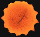
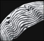
A porosity map of an aluminum intake manifold casting is shown (left). A scan reveals a micro stress fracture in a ceramic drill bit (right).
A porosity map of an aluminum intake manifold casting is shown (left). A scan reveals a micro stress fracture in a ceramic drill bit (right).
Could detecting and quantifying the internal flaws of complex parts be as easy as operating a microwave oven? Kevin Legacy, manager of computed tomography (CT) and engineering at Carl Zeiss IMT Corporation (Maple Grove, Minnesota), thinks so. He compares the manufacturer’s Actis line of industrial CT systems to the one-button operation of the kitchen appliance.
“The operator places the part on a rotary table that is located between an X-ray source and an X-ray detector,” Mr. Legacy explains. “The user then closes the door and sets the appropriate parameters. This frees up the user to work on something else until the system is finished.”


This may sound simple, but the technology is anything but. The Chicago, Illinois-based Bio Imaging Research (BIR) invented the medical CAT scanner design that most of us are familiar with today. In concert with BIR, Zeiss has developed not only a line of systems appropriate for use in the industrial setting but also a CT software module based on its Calypso CMM software.
The technology has the potential for more widespread use in machine shops. Using this non-destructive testing tool, shops can capture data related to internal part flaws before machining cycles begin. After machining, the CT system measures internal features, which makes it fitting as a complement to CMMs. It is even more fitting as a complement to non-contact optical scanners that cannot readily capture data from internal cavities, undercuts or deep recessed portions of certain parts.
Identifying internal part defects usually occurs too late in the process, ultimately causing machine shops to write off hours of machining time associated with flaws that are revealed during the cutting process. Using an industrial CT system, however, companies can take corrective measures to address problems early on. When dealing with castings, unchecked porosity can lead to assembly leaks or failures, resulting in warranty costs. Therefore, this capability can be particularly useful to facilities that machine their own castings. These facilities can use CT data to dial in the casting process so that porosity and wall thicknesses are consistently correct.
“Even if a shop is comfortable with its casting supplier, it should consider this,” Mr. Legacy says. “The technology should be used primarily as a casting process control tool and secondarily as an inspection tool.”
Although this technology does not yet offer the accuracy and repeatability of a CMM, it does provide a means to face challenges that are problematic with other devices. According to Zeiss, CT systems provide:
- Non-destructive detection of delaminations; cracks; voids and inclusions; and core shift and state information.
- Reverse engineering of the complete part because the scan provides a dataset that is inclusive of all internal “hidden” features, passages and so on.
- Scanning through packaging (as might be necessary in the medical industry)
- Non-invasive patent infringement analysis.
“Based upon what shows up on this scan, companies might re-evaluate processes,” Mr. Legacy explains. “For example, wall thickness results can be used to identify the best areas for fixture clamping. This could minimize clamp-induced part stresses, help optimize the overall machining process and produce more consistent part geometries.”
Shades Of Gray
CT images are created when X-ray beams are projected through the object. As the X-rays pass through the object, some radiation is absorbed; some is scattered; and some is transmitted. The radiation that is transmitted is measured and used to reconstruct a mathematical representation of the object. This process is repeated as the object is turned, which ultimately leads to the reconstruction of a 4D model (XYZ coordinates and density).
The X-rays can also be used to produce cross-sectional views of a part. These grayscale slices reveal both internal and external features. Once a series of slices is generated from the part, a Stereolithography model (STL file) is reconstructed from the slices. The model can be merged with the CAD model in a variety of software applications, which creates a variance map of the two data sets.
“STL files generated from CT data can be used by the CAD/CAM engineer to optimize the design,” Mr. Legacy explains. “The engineer could then test it using finite element analysis and ultimately create a more aggressive machining program.”
Zeiss’ module for Calypso software allows the CMM software to read a CT data file, and process that file and report the results as if it were data derived from a CMM. The basic file format for CT is TIFF, 2D images that display the internal features of an object in grayscale. The intensity of the grayscale is determined by the amount of attenuation in the X-rays that pass through the part. Air, which has no density, appears black in a CT image while denser materials appear in lighter shades of gray all the way to white.
While Zeiss and BIR are working on technology to move CT from the lab to the shop floor, they acknowledge that they are not quite there yet.
“It will probably be a few years before machinists start to use CT for their own setup needs,” Mr. Legacy says.


Related Content

Understanding New Surface and Profile Standards
Standards for surface finishes and profiles are not static; they change as technology changes or new processes come along that need to be considered.
Read More
More Surface Finish Parameters at Hand
Measuring surface finish at the point of manufacture is often done by the same machinist who is manufacturing the part. They need tools that meet test requirements and are easy to use.
Read More
Machined Part Geometry Measurement
Uncertain about uncertainty? Having trouble remembering the difference between accuracy and precision? Read on to review key metrology terms relevant to the ISO Guide to the Expression of Uncertainty in Measurement (ISO GUM).
Read More
Measuring Torque, Thrust Force for Smart Drilling Operations
To monitor drilling operations for smart manufacturing solutions, torque and thrust force can be measured.
Read MoreRead Next

OEM Tour Video: Lean Manufacturing for Measurement and Metrology
How can a facility that requires manual work for some long-standing parts be made more efficient? Join us as we look inside The L. S. Starrett Company’s headquarters in Athol, Massachusetts, and see how this long-established OEM is updating its processes.
Read More