
Machining 101: What is Five-Axis Machining?
Five-axis machining offers increased productivity and geometric flexibility, but the additional axes of motion can compromise rigidity and accuracy.


Five-axis machining adds rotational movement to the traditional three axes of linear motion (X, Y and Z). These machines can incorporate an A-axis that handles rotation of the X-axis, a B-axis that does the same for the Y-axis, or a C-axis that rotates about the Z-axis. Some employ rotary, tilting tables, which provide mechanical and thermal stability alongside improved access for swarf removal. Others employ a pivoting spindle head to accommodate larger, pallet-loaded parts.
Applications of Five-Axis Machining
Five-axis machines can operate as five-axis positioning or five-axis contouring machines.


In a positioning machine, the two chosen rotational axes are capable only of indexing, and cannot move simultaneously with the three linear axes. This limits machining to three-axis features. However, the increased positioning flexibility can enable machining multiple sides of a workpiece in a single setup while also improving spindle access to the workpiece for undercuts and difficult-to-reach geometry.
Five-axis contouring machines enable axis orientation changes at the same time as linear position movement. Geometries of parts that use this type of machine fall into two broad categories: ruled and arbitrary surfaces. Ruled surfaces are those where, at any given point on the surface, the user can extend a line from one edge of the surface to the other. These surfaces are suitable for point milling (which uses the tip of a ball, bull or tapered ball end mill) as well as flank milling (which uses the side of tapered or cylindrical end mills). Arbitrary surfaces, in comparison, are suitable only for point milling. Many parts contain both ruled and arbitrary surfaces.
Benefits of Five-Axis Machining Technology
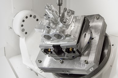
Granting users access to five sides of a part in a single setup enables tighter tolerances. Parts with 3D contoured surfaces (such as mold cavities and electrodes) tend to be great candidates for five-axis machining. For example, flexibility in accessing deep cavities enables shops to use tool assemblies with reduced lengths and aspect ratios for these operations.
Improved tool orientation control also helps with tool breakage and chatter when working with difficult-to-machine materials. For example, the surface speed of a ball mill depends on the contact angle between tool and surface. On three-axis equipment, this angle changes as machining proceeds. When the bottom of the ball mill contacts the part, surface speed becomes an unproductive zero. Surface speed then reaches its peak when the tool’s equator contacts the part. These variations in surface speed cause variations in surface finish, create premature and unpredictable tool wear, and reduce productivity.
This static orientation is analogous to five-axis positioning, in which the angle of the tool is set before it contacts the workpiece. Although the tool angle is fixed, productivity is generally still higher than three-axis machining, especially when the workpiece surface is fairly regular. Active orientation enables five-axis contouring: the angle of the tool changes relative to the machine axes in real time. This enables a constant angle and surface speed, leading to higher programmed feed rates and better surface finishes.
Orientation control also boosts performance of flat-bottom and bull-nose end mills that need a constant 5- or 10-degree angle between the cutter axis and the plane normal to both the surface tangent plane and the direction-of-motion plane. The angle increases the effective radius, reducing the scallop height, improving surface finish and reducing the number of tool passes required to complete the operation. Controlling tool orientation also enables a constant depth-of-cut and accounts for variations in the stock-on condition of parts.
Drawbacks of Five-Axis Machines
Five-axis functionality comes with a learning curve — shops adopting five-axis for the first time cannot expect plug-and-play success. Machining strategies will require reconfiguring tailored to the specific part family under production. The machine, the CNC and the CAM software are likely to be more expensive than comparable three-axis versions. Additional axes of motion introduce additional sources of error and potentially compromise rigidity. In short, five-axis is a high-yield process, but it is also higher-risk.
Initially operating a five-axis machine like a three-axis machine may seem like a waste of capability, but it can help users become more familiar with the machine while they learn.
Selecting a Five-Axis Machine
While many different five-axis machine configurations exist, this section aims to cover four common varieties.
Compound rotary tables are the most straightforward and economic way of getting five-axis performance, but they come with several significant drawbacks. These tables can be added to three-axis machine tools, but are less stiff and possess higher angular errors than more integrated approaches. Stacking the rotary axes on top of each other further magnifies angular errors, and the large stack-up between workpiece and rotary axes with a double-tilt rotary means high-torque loads affect the gear sets, reducing life and increasing deflection. Long axis travels also become necessary to maintain contact between the workpiece and the tool tip, potentially increasing errors and limiting effective material removal rates. Tables also generally require a large machine tool relative to part size. These factors make compound rotary tables best suited for five-axis positioning applications and five-axis contouring of less-demanding small components.
Two-axis spindle heads, also called spindle heads, typically see use on gantry-type machining centers. They suffer the same accuracy and stiffness weaknesses as double-tilt rotary tables, and can have limited rotational range (for vertical machining, the C-axis will typically have an unlimited range of motion, while the A-axis might be limited to ±90 degrees of motion from the vertical position). They remain desirable for accessing large and deep cavities, which are common among large mold and die components for the automotive industry. These heads are not recommended for long, slender parts like blades and propellers, where 360-degree access is often necessary.
Single-axis spindle heads, often called “pendulum-type” heads, generally provide better accuracy than double-tilt tables or multi-axis spindle heads because the rotary axes are not stacked. In a vertical machining center, the five axes are typically distributed in a three-axis set (X, Y and either A or C) and a two-axis pair (Z and either B or A). Unfortunately, the center of rotation of the spindle head is relatively far from the tool, causing angular errors and decreasing overall system stiffness, and range of motion is often limited. These configurations still perform well for impellers, blades and other parts where the part itself can rotate to present different faces to the spindle.
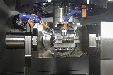
The tilting spindle, when combined with a single-axis rotary table, is generally the best choice for five-axis machining of small- to mid-size concave and convex components. Prismatic and long, slender parts are particularly well-suited for this configuration. The B-axis enables the spindle to rotate around the tool tip, minimizing angular errors and keeping torsional loads on the B-axis to a minimum. Even when the tool tip is not perfectly aligned with the center of B-axis rotation, the distance between the tool tip and center of the rotation is usually less than 3 inches, reducing angular errors by 75% or more. The tilting spindle design enhances accuracy by ensuring that linear axis motions are kept at a minimum when large B-axis angular motions are required. The separation of the two rotary axes minimizes stack-up error, and ±100-degree spindle head rotation from the vertical both increases flexibility compared to other machine types and assists in the creation of undercuts. This undercut capability makes tilting spindle machines well-suited for components like tire patterns, complex electrodes and turbo-machinery components. Conversely, the limited throat distance between the spindle centerline and the face of the B-axis gear set limits this design’s performance for machining deep cavities in large-diameter parts.
Effect of Five-Axis Design Upon Machine Performance
Pendulum and double-tilt rotary designs have tool-part interfaces much farther from the center of B-axis rotation than tilting spindle five-axis designs. This distance multiplies angular errors by about 250 (not percent, but the actual value). This makes the tilting spindle design far more accurate, even with smaller axis travels and a lower axis feed rate that achieves the same surface speed. Accuracy is especially important given how tolerances must account for margins of error not just with one axis, but across all five — and this before adding dynamic errors, thermal effects, tool run-out, deflection and other issues.
Swift CNCs are also a must in five-axis machining. Five-axis machining creates more information than three-axis machining, especially with constant linear-axis movement to maintain tool-work contact. It is worth checking whether the block processing rate will stay over 1,000 blocks per second, which is the recommended CNC speed for high-performance five-axis simultaneous contouring.
CNC and Motion Performance
Specific features that are useful for five-axis CNC include five-axis tool length compensation and part compensation, which eliminate the need for the user to repost the tool path if the actual tool length or part size differs from the nominal value. Large computer storage drives (either cloud-based or local), as well as wired Ethernet or wireless connection capability, help accommodate the transfer and storage of the large part programs necessary for five-axis parts.
Five-axis CNC systems should also have robust error recovery routines because of complex parts’ expense and long cycle times. Power failures and broken cutters are always a risk as well. These recovery routines should include the ability to retract the tool along its major axis.
While axis feed rates are an excellent evaluation criteria for three-axis machines, they are significantly flawed for five-axis machines. Instead, machine geometry and user applications dictate whether the rotary axes or the linear axes dictate five-axis performance limits. For example, tilting axis machines have higher linear feed rates and B-axis speeds than comparable pendulum geometries, but will have lower cutting feed rates. This balances out by pendulums being swifter, but with lower stiffness and 250 times worse accuracy.
Spindle Selection
As is the case with three-axis spindle selection, users must balance top-end spindle speed against low-end torque, especially for high-performance machines. However, five-axis machines offer additional features that can significantly impact performance.
Five-axis spindles must operate in many orientations, including “nose up.” This means front-bearing sealing arrangements must be high-quality for long spindle life. The tool-spindle interface is also important for work involving deep cavities, complex geometries or difficult-to-machine materials. HSK spindles are best for these tasks, especially with tools with diameters larger than 0.5 inch, as they are more rigid and accurate than comparable CAT/ISO taper geometries. They also are more resistant to long-term fretting, which occurs when flank milling hard materials over extended periods of time or when working with long tools to gain access to complex geometry.
Thermal Performance
All five-axis machines are susceptible to thermal growth, but double-tilt rotaries and pendulum-type spindles are particularly vulnerable. Users can manage thermal performance with CNC-based thermal growth control systems, which reduce spindle thermal growth reduction by as much as 85%. Direct, linear scale feedback on the X, Y and Z axes, and high-resolution-output shaft encoders on the rotary axes, can also minimize the effects of thermal growth. With no countermeasures, thermal growth can affect accuracy by 0.002 inch or more over several hours.
CAM Selection for Five-Axis Machining Technology
Wide variation in five-axis machines and processes makes choosing the right software critical. For example, does the software only offer static tool orientation control, or more flexible contouring? Does it offer collision detection and control? Has the provider tested the CAM software on in-house five-axis machines? A simpler piece of software may be cheaper, but additional functionality and flexibility will prove more productive in the long run.
For recent topics in five-axis machining, visit the MMS Five-Axis Machines information zone.


Related Content

Volumetric Accuracy Is Key to Machining James Webb Telescope
To meet the extreme tolerance of the telescope’s beryllium mirrors, the manufacturer had to rely on stable horizontal machining centers with a high degree of consistency volumetric accuracy.
Read More
Choosing a Five-Axis Machine Tool With Automation in Mind
While much focus is placed on the machinery that moves parts, the features most important for automating five-axis machining are arguably found in the machine tool itself.
Read More
Choosing Your Carbide Grade: A Guide
Without an international standard for designating carbide grades or application ranges, users must rely on relative judgments and background knowledge for success.
Read More
Inside an Amish-Owned Family Machine Shop
Modern Machine Shop took an exclusive behind-the-scenes tour of an Amish-owned machine shop, where advanced machining technologies work alongside old-world traditions.
Read MoreRead Next

The Cut Scene: The Finer Details of Large-Format Machining
Small details and features can have an outsized impact on large parts, such as Barbco’s collapsible utility drill head.
Read More
3 Mistakes That Cause CNC Programs to Fail
Despite enhancements to manufacturing technology, there are still issues today that can cause programs to fail. These failures can cause lost time, scrapped parts, damaged machines and even injured operators.
Read More
