Machining 101: What is Grinding?
Grinding takes an abrasive — often attached to a wheel — and uses its many grains to cut a workpiece. Variations on this process are useful for a wide variety of applications.

Share


On its surface, grinding seems simple: a machine takes a rotating tool (usually a wheel) with abrasive grains and applies it to a workpiece’s surface to remove material. Each grain is its own miniature cutting tool, and as grains dull, they tear from the tool and make new, sharp grains prominent.
But there are many variations, approaches and considerations for this type of machining, each of which is particularly effective for certain applications with certain materials.


Principles of Grinding
In all forms of grinding, three different interactions occur between the abrasive and the machined material. Cutting occurs where the abrasive grain is sufficiently exposed to penetrate the workpiece material and curl a chip, and sufficient clearance exists between the grain, bond and workpiece to flush the chip with coolant or throw it away by wheel action. Plowing takes place when the grain is unable to get enough penetration to lift a chip, instead pushing the material ahead of the abrasive edge. Sliding happens when a lack of cut depth, insufficient clearance or a grit staying on the wheel after dulling results in rubbing or creating slide marks on the workpiece surface. Grinding process control balances these three interactions to achieve the desired parameters.
These interactions feed into three major commercial grinding processes: rough grinding, precision grinding and ultra-precision grinding. Rough grinding maximizes the metal removed at the cost of surface finish. It primarily sees use in cutting off billets, grinding weld beads smooth and snagging gates and risers from castings.
Additional surface finishing passes typically take place afterward — in particular, a “spark-out” pass relieves some of the stress on the machine tool and uses plowing to impart a better surface finish and size tolerance. Precision grinding is a middle-ground between metal removal and part size control, and serves as the basis for creep feed grinding, slot grinding and high-efficiency deep grinding. In ultra-precision grinding, little to no actual cutting occurs, but sliding action from very fine grains rubs the workpiece surface to a high finish. Most surface finishing processes, such as lapping and polishing, are examples of this type of grinding.
Hundreds of different variables can affect the interaction between the abrasive and the workpiece, but they generally come down to machine tool, work material, wheel selection and operational factors. Balancing these by setting up a part run that fits within the known parameters of all four categories provides a baseline that gradual parameter adjustment can improve.

Grinding Wheels
Grinding wheels have two major components: the abrasive grains and the bond. The relative percentages of grain and bond, and their spacing on the wheel, determine the wheel’s structure. Different types of grains work better on different projects, as do different types and “grades” (i.e. strengths) of bond. Broad areas of grinding need coarser grits and softer grades, with smaller areas requiring finer grits and harder grades to withstand the greater unit pressure.
Straight wheels are the most traditional type of grinding wheel, with the grinding face on the periphery of the wheel. Recessed wheels are variations on this form, featuring a recessed center to fit on a machine spindle flange assembly. The other major type of wheel shape uses a cutting face on the side of the wheel — names for this type of wheel include cylinder wheels, cup wheels and dish wheels, depending on the particular shape. For these wheels, bonded abrasive sections of various shapes, also known as “segments,” are assembled to form a continuous or intermittent side grinding wheel.
Operational Basics
Although speeds for grinding wheels are measured in sfm or smm, wheels are often rated in rpm. It is important never to operate a grinding wheel over its rpm limit — most experts recommend never mounting a wheel on a machine that can exceed the wheel’s limit.
As speeds increase, each grain cuts and wears less. This emulates a harder grade. Vitrified bonds work up to 6,500 sfm, with organic bonds handling up to around 9,500 sfm. Higher speeds will require specially made grains.
Work speed defines the speed at which a grinding wheel passes over a workpiece or rotates around a center. High work speeds lower the heat retention and reduce the risk of thermal damage. Both high work speeds and reducing the diameter of the wheel result in increased grain depth of cut, performing like a softer grade wheel.
Traverse distance, or crossfeed, is the distance a workpiece moves across the face of the wheel. Lowering the traverse distance to no more than one-quarter of the wheel width improves surface finish, but slows down productivity. Increasing the crossfeed to one-half the wheel’s width or above boosts productivity, but lowers surface finish.
Different types of grinding use different methodologies to determine the work material removal per unit of width, but one consistently useful metric for shops is the grinding gratio, or g-ratio. This is the ratio of volume of work removed to volume of wheel consumed (or, volume of work removed ÷ volume of wheel worn). From a cost standpoint, a higher g-ratio is better.
Types of Grinding
Grinding operations come in many types, with this article covering six major types and several of the subtypes within.
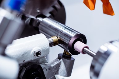
Cylindrical grinding is a common type of grinding in which both the wheel and the workpiece rotate. The workpiece is either fixed and driven between centers, or driven by a revolving chuck or collet while supported in a center. This operation can take place with either traverse movements, where the wheel traverses axially along the part, or plunge movements, where the wheel is thrust into the part. Straight wheels are most commonly used in cylindrical grinding, with common cylindrical grinding machines being plain cylindrical (or roll) grinders, centerless grinders and inside- or outside-diameter grinders. Internal cylindrical grinding does the internal diameter grinding of bores and holes, generating size and concentricity within millionths of an inch. The grinding wheels tend to range in diameter from half an inch to three inches. This small size introduces rapid wear, making CBN and diamond wheels in crush dressable and vitrified form popular for these applications.
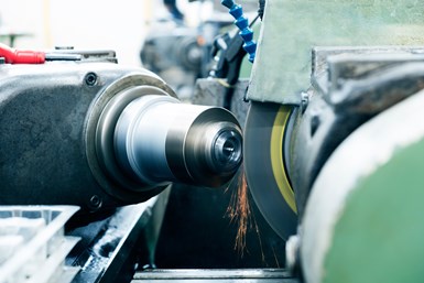
Surface grinding involves grinding a plane surface by feeding the workpiece beneath a rotating grinding wheel. Like cylindrical grinding, it operates in two general formats. The workpiece may travel traversely under the wheel and move back and forth beneath a grinding wheel mounted on a horizontal spindle, or it may move in circles on a rotary table beneath a vertical spindle that cuts on the face of the grinding wheel or grinding segment. Applications for this grinding type may grind a surface flat or introduce grooves by grinding straight channels into the workpiece. While milling can complete these tasks, grinding improves surface finish, has less expensive tooling and allows contours to be dressed into the profile of the wheel — making it much more cost-effective for very hard or abrasive surfaces.
Centerless grinding creates cylindrical forms at extremely close tolerances. This type of grinding eliminates the need for center holding by supporting the workpiece at three separate points: the grinding wheel, feed wheel and work support blade. Nothing actually clamps the workpiece in place, so each piece flows freely for continuous production (also known as “throughfeed centerless grinding”). The grinding wheel and the feed wheel rotate in the same direction, while the workpiece rotates in the opposite direction between them. The rotation keeps the workpiece down, while the work support blade (slightly angled to raise the workpiece above the centerline for better cylindricity) holds it up. The work support blade should always be at least as long as the grinding wheel is wide.
Centerless grinding also comes in three forms. Throughfeed centerless grinding is used on straight cylindrical workpieces without interfering shoulder or projections, and involves the offset axis feed wheel feed the workpiece past the grinding wheel to a discharge position. Infeed grinding (also called plunge centerless grinding) is best when a workpiece has projections, irregular shapes, varying diameters or shoulders, and works best for profiles and multi-diameter workpieces. In this submethod, feed wheels above the grinding wheel feed the workpiece downward, with no lateral movement during grinding. Endfeed centerless grinding grinds conically tapered cylindrical sections like shanks on A and B taper drill bits. Here, the feed wheel, grinding wheel and work blade are set up in a fixed relationship to each other, then two wheels are dressed to a shape matching the end taper of the workpiece and the workpiece is fed from the front of the grinding machine until it reaches an end stop.
Creep feed grinding is a slow, one-pass operation that makes a deep cut of up to one inch in steel materials at low table speeds between 0.5 and 1 ipm. It is not suitable for conventional grinding machines, but for those which are compatible with it, it offers high productivity and cost effectiveness. Creep feed grinding is a plunge operation with high horsepower requirements, and which also requires a heavy flow of cutting fluid close to the nip to remove chips and cool the work. Continuous dressing at about 20 to 60 millionths per revolution — preferably with a diamond roll — reduces cutting times and keeps the wheel sharp. When a second pass is required, it is typically of no more than 0.002 inch deep to “clean up” the workpiece.
Snagging is a rough grinding application that removes unwanted metal with little consideration of surface finish. As such, it uses durable straight and straight cup wheels in horizontal and straight shaft grinding machines, although flaring cup wheels are used in right-angle grinders and various round and square-tipped cones and plugs also see use. Typical applications include removing unwanted metal on castings; removing flaws and cracks; removing gates, risers and parting lines; rough beveling; grinding down heavy welds; and preparing surfaces for cleaning or painting.
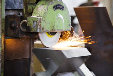
Cut-off operations use an abrasive wheel as an alternative to the laser, abrasive water jet, metal saw, friction saw and oxyacetylene or plasma arc torch. A study from Norton Abrasives demonstrated that the abrasive wheel can outperform these other methods with ferrous materials, and that the abrasive wheel is faster and less expensive for nonferrous materials than the common metal saw choice. The abrasive wheel provides more cutting points than a saw, and cuts just as thoroughly at a speed of 2 or 3 miles per minute. Cut-off wheels should run at the highest possible speed, with one horsepower for every inch of wheel diameter. If this proves impossible, use a softer wheel. Production jobs use non-reinforced wheels, with non-reinforced shellac wheels for applications requiring extreme versatility and quality of cut. Reinforced wheels are compatible with portable cut-off, swingframe, locked head push-through and foundry chop stroke operations.

Considerations for Grinding Tool Steels
Improperly grinding tool steels can affect their performance not only through the formation of grinding cracks that will lead to eventual breakage, but by developing a softened surface zone. Burning may only appear slight on the surface, but the softening can continue under the surface (and in fact, burning can slightly reharden the surface, showing a hardness profile that is softened on top, then hardened, then soft again). The depth and hardness of the burned zone will vary considerably within the affected area to due mechanical conditions of grinding like coolant flow, rate of wheel breakdown, chatter and more.
Superabrasive Machining
Superabrasives are diamond or CBN (cubic boron nitride) grinding wheels or mounted points. These grind extremely hard materials, with CBN working on hard steels for precise profiles and finishes, and synthetic diamond working on hard nonferrous material like tungsten carbide and cermets. Superabrasives can be used for both roughing and surface finishing, depending on the grit size involved. The core material of the wheel also has a direct influence on its performance characteristics, and should be selected to meet operation requirements.
Dressing Grinding Wheels
Dressing and truing grinding wheels prepare them for service and ensure proper accuracy for the grinding operation. Truing involves making the periphery of the wheel run concentric to the axis of rotation, and may require alerting the wheel by forming a special contour into its face. Dressing alters the cutting action of the wheel when the hard diamond point of a dressing tool breaks the bond posts of a vitrified wheel and fractures the grains, removing dull ones and making the new ones sharp. Dressing also picks up tiny pieces of material from the pores of the wheel face, ensuring that they do not slow the grinding process and cause burn or chatter.
Conventional dressing wheels do truing and dressing simultaneously with a light cut, while superabrasives require truing with a tool or roll, and separate dressing with a vitrified dressing stick. Before truing a superabrasive wheel, use a wax crayon over the wheel face — the process should eliminate all crayon marks by the end. Dressing a superabrasive will require direct application of a vitrified dressing stick (often aluminum oxide or silicon carbide, but sometimes high-performance norbide or boron carbide).
Superfinishing
Even with the finest grits, grinding is a high surface-temperature operation that produces peaks and valleys. The surface will also be minutely wavy, with chatter marks that are invisible without magnifications but devastating during high-speed rolling or sliding. Superfinishing will be necessary to remove surface finish peaks and provide a good hardness, structure and load-bearing surface of undisturbed base metal.
Parts that require superfinishing include roller bearings, shock absorber rods, sliding vane pumps, piston pins, crankshaft journals and cam lobes. In this process, a finishing stick oscillates rapidly with a very short stroke while the workpiece rotates. As the abrasive oscillates, the workpiece rotates or oscillates under a cup or cylinder, producing microfine chips. The process removes as little as 0.5 micron (0.00002 inch) or as much as 20 microns (0.008 inch) of material. Superfinishing is also known as microfinishing, polishing, short stroke honing or superhoning (but never just “honing,” which is a separate process).
Measuring the surface finishing in superfinishing can take one of two stylus types. Skid styli are not fully representative of the surface, as they may amplify or nullify the waviness of a surface depending on how the geometry relates skid-stylus spacing. These styli are best for roughness assessments that eliminate the factors of waviness and error of form. Skidless styli better represent the surface’s waviness and form, creating a more accurate profile.
For recent topics in grinding, visit the MMS Grinding information zone.


Related Content

4 Tips for Staying Profitable in the Face of Change
After more than 40 years in business, this shop has learned how to adapt to stay profitable.
Read More
Where Micro-Laser Machining Is the Focus
A company that was once a consulting firm has become a successful micro-laser machine shop producing complex parts and features that most traditional CNC shops cannot machine.
Read More
Additive/Subtractive Hybrid CNC Machine Tools Continue to Make Gains (Includes Video)
The hybrid machine tool is an idea that continues to advance. Two important developments of recent years expand the possibilities for this platform.
Read More
Addressing Manufacturing Challenges with Automation
GrayMatter Robotics’ Physical AI robotic cells for manufacturing offer immediate impact and results.
Read MoreRead Next

OEM Tour Video: Lean Manufacturing for Measurement and Metrology
How can a facility that requires manual work for some long-standing parts be made more efficient? Join us as we look inside The L. S. Starrett Company’s headquarters in Athol, Massachusetts, and see how this long-established OEM is updating its processes.
Read More