
Methods and Benefits of Designing for Additive Manufacturing
Additive manufacturing may have different process considerations than traditional manufacturing, but it can manage these through clever planning and specialized software.

Share


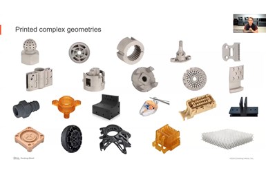
Additive techniques can create parts in a wide variety of shapes, many otherwise impossible to manufacture. However, users must leverage design tools and strategies that compensate for AM’s quirks. Image courtesy of Desktop Metal
In a webinar from August 2021, Ethan Rejto, technical marketing manager at Desktop Metal, said design for additive manufacturing (DFAM) can be broken into two categories: leveraging design features to take full advantage of additive manufacturing (AM), and following rules to be successful with the process. He also discussed tools that support DFAM, drawing from examples of technology offered by Desktop Metal and its partner companies.
Additive Geometries
Complex geometries have been possible through traditional manufacturing methods, but Rejto points out that they resulted in narrower design spaces, increased cost and increased manufacturing complexity. AM has greater design flexibility, requires less material — thereby lowering costs — and does not increase in manufacturing process complexity with increased part design complexity. Rejto went so far as to say that additive manufacturing can “create parts that would take decades of knowhow for traditional manufacturing in the push of a button.”


Lightweighting is a notable advantage stemming from increased geometric complexity. Even basic optimizations can greatly reduce costs and print times, but the most significant advantages come from advanced lattice-work (which often requires dedicated topology optimization software). Lattices can further drop the weight and cost of optimized parts, while creating geometries impossible or unfeasible for traditional manufacturing.
Traditional manufacturing has always been able to handle straight holes, but additive manufacturing enables more shapes. This benefit comes into play most often when working with manifolds or designing conformal cooling channels with untraditional shapes. Cycle times for parts decrease, and the daily production capacity for parts in question increases drastically.
Non-circular holes are also simpler to create with additive manufacturing. Rejto showed off an atomizer for a liquid natural gas tanker where the fuel efficiency increased by 67 percent after a change from a traditional atomizer design to one with internal pathways and teardrop-shaped outlets.
Modern printers can also accomplish high-resolution printing, printing layer-by-layer at micron heights to create fine details or textures. Print-in-place assemblies can also use links, hinges and gear sets to join sections on a single assembly.
Rejto pointed to the GE Leap nozzle as an example of most of these improvements. Through DFAM, GE consolidated the assembly from 20 parts down to one, reduced its weight by 25 percent, lowered cost by 30 percent and reduced inventory by 95 percent. The nozzle proved five times more durable with the additively manufactured construction, and facilitated deployment time savings over 80 percent. GE shipped 30,000 parts over three years, which Rejto said is high-volume for laser powder bed fusion, but less than is needed for mass-production — and less than additive manufacturing technology can handle today. Certain printing methods now enable individual printers to manufacture tens of thousands of parts per year, and with printer farms and efficiency upgrades, manufacturers could print millions of parts per year.
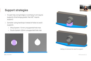
Long bridges and overhangs, large holes and steep angles require supports for successful printing. Clever use of ribs or different hole shapes can circumvent this requirement, however. Image courtesy of Desktop Metal.
Designing for AM’s Process Capabilities
Every form of manufacturing requires working around certain constraints. Examples might include tool access and cavity depth for machining; uniform wall thickness or shrinkage issues in castings; and ejector marks or undercuts in metal injection molding. Additive manufacturing can bypass some of these design constraints, but others also come to the fore.
Rejto identified additive manufacturing’s largest process concerns as tolerances, sintering success, support strategies, maximum and minimum wall thicknesses, aspect ratios and depowdering strategies.
Tolerances are especially an issue when AM processes that involve sintering furnaces. Parts shrink roughly 20 percent in the furnace, which can lead to difficulties holding geometric tolerances. Rejto said Desktop systems are able to predict dimensional capabilities to about ±0.8 percent, but for critical dimensions, he recommended secondary processing — be that CNC machining, EDM, grinding or any other method. AM parts are also fully compatible with traditional finishing operations, heat treating and welding.
Manufacturers also must plan to correct for the forces the part will experience during the sintering process. These include gravity drop, shrinkage pull, density warp, friction trip-up and centroid rotation. Large unsupported overhangs can cause additional problems, while large variations in mass can induce cracking due to sections of the part shrinking at different rates. Edges should also have a radius (fillet) of at least 0.5 mm to avoid issues at the sintering oven.
Supports may need to be designed into parts with long bridges or overhangs. In general, overhangs greater than 60 degrees require support. Large, circular holes can also require supports, and Rejto recommended changing the shape of the hole to a teardrop or diamond in these circumstances. Adding a rib can also remove the need for a support.
Ensuring parts have a workable aspect ratio is another important design aspect for additively manufactured parts. Tall, thin features run the risk of toppling or warping during sintering. The particular ratio of height to thickness required for proper sintering varies based on the equipment. Hand-in-hand with this issue is the maximum and minimum wall thickness AM parts can handle. A minimum wall thickness ensures parts are structurally sound and can be handled in the fragile green state. The maximum wall thickness ensures that parts can release all binder during sintering. This is important because unsintered binder can crack the part.
For binder jetting, parts need to be excavated from their build box after the printing process. During this depowdering stage, parts are in a green state and are quite fragile, so effective depowdering requires access via a brush or compressed air. The need for radii on edges is particularly important here, as thin “knife edges” are prone to chipping and breaking during depowdering. In contrast to some other types of additive manufacturing, complex inner channels can cause problems for binder jetting during the depowdering process if users can’t reach inside them to remove loose powder.
Tools for DFAM
Traditional CAD software can do much for DFAM, but other, specialized pieces of software can explore the wilder possibilities of AM.
Traditional CAD is capable of basic assembly consolidation, changing hole shapes to increase supports, adding fillets or chamfers and even performing simple lightweighting. Once the user is experienced with CAD software, performing these tasks may only take between five and 15 minutes.
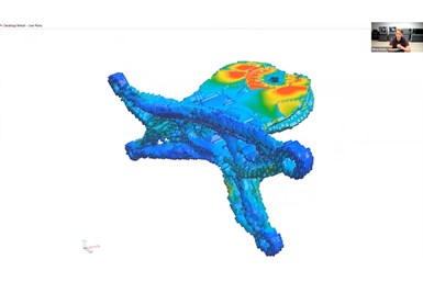
Generative design creates organic forms that can be impossible to machine. These forms are optimized for specific load requirements while using the minimum material required. Image courtesy of Desktop Metal
Generative design takes an organic approach: after inputting part objectives and some basic parameters, the software grows a part by adding material where stresses are high and removing material where stresses are low. Rejto pointed to Desktop Metals’ Live Parts as an example of this sort of software, and showed a part the software generated into an organic shape that would be hard or impossible to fabricate through traditional manufacturing methods, but simple with AM.
Topology optimization can set loads, boundary conditions and constraints to optimize material usage. As with generative design, the resulting geometries are typically extremely difficult or impossible to produce via regular manufacturing methods. Lattice generation software takes this same approach, transforming thick geometry sections into lattices and adjusting cell size, thickness and structure to create the desired lattice. This dramatically reduces weight while retaining structural integrity. Rejto pointed to nTopology as an example of both topology optimization and lattice generation software.
Nesting and support generation software automatically prepare supports for parts when necessary and nest parts into the build box. This simplifies the printing of end-use parts. Rejto said Desktop uses its in-house Fabricate MFG software to accomplish this for metal parts, while its subsidiary EnvisionTEC uses its Envision One RP software to do the same for polymers.
Rejto also discussed Live Sinter, a Desktop Metal-developed piece of software that simulates the forces a part will experience during sintering to generate a pre-distorted geometry for printing. After sintering, this geometry will emerge from the furnace straight. The goal is to control deformation and shrinkage, reduce stress concentration and improve density uniformity.


Related Content

Additive/Subtractive Hybrid CNC Machine Tools Continue to Make Gains (Includes Video)
The hybrid machine tool is an idea that continues to advance. Two important developments of recent years expand the possibilities for this platform.
Read More
Why This Moldmaker Thinks Every Shop Needs a 3D Printer
See how this mold shop uses polymer, carbon fiber and metal 3D printers to boost precision and productivity.
Read More
The Downloadable Metal 3D Printer
Copenhagen researchers introduce a fully open-source laser powder bed fusion system, now available on GitHub. This release follows their development of an open-source vat polymerization machine. Here is the purpose and promise of this philanthropically funded effort to advance additive manufacturing application and adoption.
Read More
OEMs Showcase Hybrid Manufacturing Applications
Mazak and Mastercam worked together to demonstrate the viability of hybrid additive/subtractive machining techniques at a recent event held in Florence, Kentucky.
Read MoreRead Next

OEM Tour Video: Lean Manufacturing for Measurement and Metrology
How can a facility that requires manual work for some long-standing parts be made more efficient? Join us as we look inside The L. S. Starrett Company’s headquarters in Athol, Massachusetts, and see how this long-established OEM is updating its processes.
Read More