
Slashing Programming Time For Similar Parts
There’s no reinventing the wheel for this shop! It saves machining programs in a knowledge base for use on future jobs.
Share


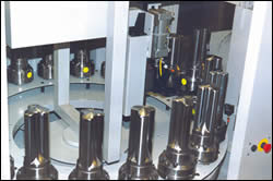
The machining center's 20-pallet carousel allows up to 20 punch or die blanks to be loaded at a time for machining, enabling the machine to run unattended for long periods.
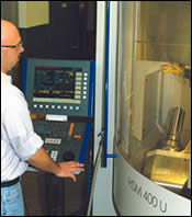
Trutron now processes most of its high speed steel, CV-joint punches and dies on this five-axis machining center, one of two high speed, hard milling machines that the company recently added.
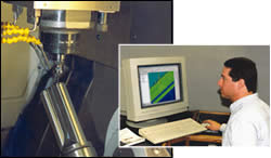
Close-up of a typical CV-joint punch being machined on the five-axis machining center. Using data from a machining knowledge base, Trutron engineering manager Mark Cohrs saves about 30 minutes of programming time per operation on parts that involve as many as 20 operations.
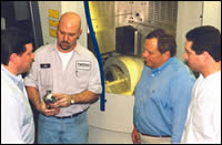
Operator Joe Adamski (holding punch) confers with Trutron vice president Tim Griswold (left), company president Dennis Carlson, Jr. (blue shirt) and Mark Cohrs.
If you're machining families of parts, you need to take full advantage of the features that the parts have in common to minimize programming, setup and machining times. That's part of the thinking that guided Trutron Corp., a CNC machining firm located in Troy, Michigan, as it sought to become more efficient in the production of a particular type of automotive tooling for which it is known—punches and dies for front-wheel drive constant velocity joints.
Trutron has made tooling for CV joints since the early 1970s. The main components of the tooling are a punch and die, both made from high speed steel barstock. The punches are typically 10 to 12 inches long by 4 inches in diameter. The dies are typically 8 inches long by 6 inches in diameter, with a 4-inch cavity. Originally, after initial sizing and heat treating of the blanks, the punch and die details were burned in by the EDM process, in keeping with the fact that the company started as an EDM company.


As the company grew, its machining capabilities expanded. It also started diversifying into aerospace work, which involved machining parts made of many different metals. In order to process the aerospace work more efficiently, the company added machining centers. Then, when high speed machining came on the scene, the company began considering the advantages of high speed machining centers for the production of graphite electrodes for its ram EDM machines and as an alternative to EDMing some jobs.
Trutron officials made the rounds of the machine tool builders and distributors that exhibited high speed machining centers at the 1998 International Manufacturing Technology Show in Chicago. They were most impressed by the machining centers exhibited by Mikron (Lincolnshire, Illinois), which offered spindle speeds up to 42,000 rpm. Some time later, the company purchased a Mikron HSM 700, three-axis, machining center, to which it added a fourth axis. Its intended use was for high speed machining of graphite electrodes as well as for high speed machining of heat treated metals up to 65 Rockwell C.
"The first time that we used the high speed mill to machine parts instead of EDMing them, we were able to eliminate 4 hours of operations on each part," explains Tim Griswold, Trutron's vice president of manufacturing. "That opened our eyes to the potential benefits of switching more work to the high speed machine."
The high speed mill is programmed off-line by Mark Cohrs, Trutron's engineering manager, using Esprit software from DP Technology (Camarillo, California). The company uses Esprit to program every CNC machine in the shop. That includes CNC lathes, machining centers, wire EDMs . . . even a CNC continuous path jig grinder.
The programming process for the high speed mill starts with a solid model created from CAD data furnished by the customer or created for the customer in-house. The software is able to identify pockets, islands, profiles and other geometric features of the solid model and organize them in preparation for creating tool paths. By grouping like features, the programmer can create tool paths for a whole group in just one step.
Next, the programmer begins to create the machining operations. When a particular operation is created for the first time, care is taken to make sure it is done right. Once the operation proves out, the programmer can save it to a machining knowledge base (Esprit's is called KnowledgeBase). Once saved, the operation can be called up and inserted in the programs for any number of similar parts. The information saved includes the type of material being machined, the cutting tool, speeds and feeds, depth of cut, and any other significant parameter.
After the programmer creates the tool paths, he or she verifies them using a rapid simulation that shows each tool taking its cut in the solid model. Each tool path is compared to the model, and any deviations are displayed in color. Any problems are corrected before the program is downloaded to the machine.
Building A Knowledge Base
To take advantage of the similarities of the Trutron CV-joint punches and dies, Mr. Cohrs began building a machining knowledge base that would allow him to copy pieces of existing programs and paste them into machining programs for similar punches and dies. "There are 20 to 30 different values that we keep track of in our machining knowledge base," he explains. "Things like spindle speeds, feed rates, stepovers, scallop height, lead in, lead out . . . an entire list of features that need to be specified for each part. After the list is set, I save that particular file in the machining knowledge base for future use.
"For example, if I need to program a new relief area for a punch, I don't have to re-specify those values for every new punch," he continues. "I simply call up the punch relief file from the database and plug it into my program.
"To completely machine a given punch requires some 20 different 3D cutter paths," Mr. Cohrs continues. "Some cuts are for roughing out the punch prior to heat treat, some for after heat treat and so on. After all the cutter paths have been finalized for a particular punch, they are then saved to the machining knowledge base. When we receive an order for a similar punch, I can apply all of the cutter paths for the previous punch that were saved in the machining knowledge base as-is or with minor tweaks. The stepovers, tool approaches, tool exits . . . everything has already been worked out and saved for future use. We don't have to start from scratch each time we need to develop a program for a new punch."
Mr. Cohrs notes that high speed machining of a punch involves many separate operations, and using the machining knowledge base saves him about 30 minutes per operation. "In some cases, the punches are so similar that the spindle speeds, stepover and many other machining parameters are identical," he adds. "I simply call them up and apply them to the new part being programmed.
"Our reuse of data from the machining knowledge base not only saves time, but also reduces programming errors," he continues. "There's no guesswork involved in programming and machining the part, because we've already worked out the bugs on previous jobs. Also, being able to program faster enables us to generate more programs in a given period."
The efficiency gains extend well beyond the programming workstation. Trutron's Mr. Griswold notes that it takes an average of 1,140 minutes to produce a part from start to finish using the EDM process, including the benchwork. Using the high speed machining process, the same part can be produced in about 570 minutes—or about half the time. "It's not just a matter of the time savings," he stresses. "By high speed machining the parts, we free up six or seven pieces of equipment, and as many employees, for other projects."
As Trutron became more proficient at machining the high speed steel CV-joint punches and dies, so much work was transferred from the EDM machines that the company invested in a second high speed machine, this one a Mikron 400U five-axis vertical machining center with an integral 20-position pallet changer.
According to Mr. Griswold, 90 to 95 percent of the company's high speed steel parts now go across the two Mikron machines. He stresses that the parts are not only produced faster by high speed machining, but that they are also more accurate and more consistent as well. "Tooling components produced by the ram-type EDM process frequently require benchwork and polishing, which creates the possibility for human error," he notes. "Benching is a tedious job and, if there's an attention lapse, a dimension can easily be lost. By contrast, high speed machining of the tooling component usually eliminates the hand operations, which means fewer errors and greater part-to-part and tool-to-tool consistency."
They Work Weekends
The high speed machines also require minimal supervision—one operator tends both machines—and they can be operated for long periods in an unattended mode. For example, the HSM 700 four-axis machining center is frequently set up with a fixture that holds multiple parts for machining, each of which can require an hour or more of machining time. Typically, parts will be loaded in a fixture before the last shift leaves on Friday night, and as many as 15 fully machined parts will be waiting when the first shift comes back on Monday.
Trutron's second high speed vertical machining center, the five-axis Model 400U with its integral 20-position pallet changer, also permits unattended machining of multiple large components, such as the CV-joint punches. Pallets, each holding a CV-joint punch for machining, rotate on the machine's pallet carousel to a loading station. A robot arm picks each in turn and loads it in the machine's machining area. Up to 20 punch blanks can be loaded on the pallets on Friday for unattended machining during the weekend.
Dennis Carlson, Jr., president of Trutron, puts his company's newly added high speed machining capability in perspective: "We view high speed machining as a more efficient tool for machining M2, M4, M50 and other high speed steels; therefore we have moved most of that work to the high speed machines. However, we also process a lot of tungsten carbide, all of which goes on our EDM machines, which explains our recent addition of a new CNC sinker EDM with a 25-position tool changer.
"We're in a very competitive business, and we need to be able to provide our customers with the most efficient process for producing their parts," he continues. "With our EDM and high speed machining capabilities, we can provide the best process, or combination of processes, for getting the customer's job done. On the software side, our programming software and machining knowledge base help us ensure that we do the job efficiently and get it right the first time."


Related Content

4 Tips for Staying Profitable in the Face of Change
After more than 40 years in business, this shop has learned how to adapt to stay profitable.
Read More
Star Cutter Drill Lineup Provides Smooth Cutting Operations
The line of internal coolant drills is well suited for applications in all fields where stainless steel is used, such as watchmaking, medical, aerospace, automotive and so on.
Read More
Gear Surface Texture Is More Important Than Ever
The interactions of gear surfaces are becoming increasingly important in applications such as automotive electric motor drive systems and aircraft turbines.
Read More
New Coolant Designed for Automotive Parts Production
Choosing the right coolant is critical for productivity, economic efficiency and machining quality.
Read MoreRead Next

OEM Tour Video: Lean Manufacturing for Measurement and Metrology
How can a facility that requires manual work for some long-standing parts be made more efficient? Join us as we look inside The L. S. Starrett Company’s headquarters in Athol, Massachusetts, and see how this long-established OEM is updating its processes.
Read More