
Smart And Efficient
Deft use of macros for 'family-of-features' NC programming allows this compressor manufacturer to do in minutes what once took hours, and get more consistent machining processes in the bargain.

Share


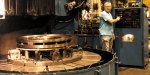
Elliott's multistage compressors go from medium size to extremely large. Each diaphragm disk is comprised of two pieces, but they are bolted together for the turning process and machined as a single piece.

How long should it take to program a part? That, of course, depends on the complexity of the workpiece. Most knowledgeable people would agree that the greater the number of features to be modeled and operations to be performed, the longer it is going to take even a skilled programmer to generate a good part program. At least that's how it would be if programming were handled in any conventional manner.
The Elliott Company (Jeannette, Pennsylvania), however, defies all normal expectations with an innovative approach to NC programming. In place of a conventional, highly interactive approach to generating tool paths, this shop's programmers have substituted custom macros of their own design that automate most of the programming process for a complicated group of turned parts. Within those programs, this shop deals with more than 250 different variables that generate turning routines with a wide range of OD, ID and face features. Combined, the macros add up to some 30,000 lines of code.


If that sounds like a lot, well, it is. But Elliott didn't get there overnight. Rather than setting out to write the mother of all programs, the programmers simplified their approach, taking it a feature at a time. And over time, they've built a system that's produced dramatic reductions in NC programming time. Indeed, some parts that once took two workdays to program are now done in as little as 15 minutes. Here's how they got it done.
A Compelling Need
Elliott Company is a leading supplier of turbochargers, multi-stage compressors, steam turbines and plant compressed air systems. As a leader in the gas compression industry for more than 70 years, Elliott's compressors are used widely in the petrochemical industry on a variety of substances including ethylene, methanol, liquid natural gas, shale oil and a number of chemicals. While the company's compressors offer a number of technical advantages (which are well outlined in its Web site www.elliott-turbo.com), what most newcomers first notice are their size. Capable of generating pressures as high as 10,000 psi or flows as high as 400,000 cfm, some units can be more than 20 feet long with rotating components up to 110 inches in diameter.
The compressor component that Elliott first identified as a good candidate for automated NC programming is the stationary diaphragm disk, which works in conjunction with the rotating impeller. Functionally, while the impeller serves to propel the gas or fluid, the diaphragm serves to guide the flow. Multistage compressors, as the name implies, include multiple sets of each. While that might sound like an opportunity to manufacture a lot of identical parts, the reality of it is quite the opposite. Many of these compressors are highly engineered products, with individualized performance characteristics. So while all diaphragms do essentially the same thing, each new one that Elliott makes always seems to do it a little differently from the last. That constant variation is what created the programming problem, and why Elliott sought to automate the programming process.
It was hardly a trivial task. Elliott produces the disks in many different sizes and with 14 different face profiles, 11 different OD styles, three different ID styles and a wide range of special features. The face profile typically includes several radii, angled shoulders and grooves with complicated blends between the various features. Most of the ODs have several tongues of various widths. The IDs are typically grooved. These variations mean that there are thousands of potential disk configurations. Moreover, design engineers are continually modifying disks in order to improve performance and reduce manufacturing costs.
An average of 20 new part programs must be created each month for diaphragms that are turned on vertical lathes. In the past, this was a challenging task given the geometrical complexity of the parts as well as the requirements for special programming touches to avoid damaging these expensive components. Because tolerances are tight for such large workpieces (+ 0.001 inch on some features), and the forgings from which they are cut are somewhat unpredictable in size, a number of touch-offs and trial cuts must be built into the programs. Another complicating factor is the variation in materials, which includes different grades of iron and alloy steels. Finally, the programs must be accompanied by detailed annotations that serve as routing instructions for the machinist.
In the past, a highly skilled engineer created these programs, often working from an archive of previously machined parts. When a new order came in, he went back and tried to find a similar part, edit the geometry, and regenerate the program. While it might take four to 12 hours to generate a new program in this manner, it still was considerably faster than importing the CAD geometry for the new design and starting to program from scratch. That would take 8 to 16 hours.
Each time the geometry was modified, the engineer had to regenerate all the tool paths required for that particular geometry. In addition, the engineer usually changed machining parameters to suit the material of the new design. He also would have to take the stock condition into consideration. Elliott produces about 100 different disk diameters that are cut from a standard selection of 40 castings. So, roughing routines have to be tailored to the stock size, but it isn't so simple as just pulling those dimensions from the casting drawing. Material size variance can be as much as a half-inch from nominal, so each casting has to be measured to determine the true dimensions, which are then factored into the part program.
Building The System
Rather than going through this whole process every time, Elliott's engineers wanted to build an expert system where all the programmer has to do is enter the critical dimensions that define a specific diaphragm disk. Thereafter, all tool paths would be generated automatically. Or at least, that was the general idea.
While the possible permutations of the diaphragm designs are many, they are still created from a relatively standard set of features. For that reason, Elliott's engineering management believed it would be possible to automate much of the programming process if they tackled it on a feature-by-feature basis, rather than trying to parametrically model the entire workpiece and machining process all at once. Based on that premise, they analyzed all of the possible part features they would have to accommodate to see if there was enough commonality to justify the effort. What they found was that, while it probably wasn't feasible to account for all contingencies in an automated environment, the 80/20 rule did apply. That is, with a reasonably manageable set of standard features that lent themselves to automated programming, Elliott would indeed be able to handle a substantial majority of the diaphragm disk configurations that are machined.
The next question was, what was the best CAM environment in which to build the system? Change seemed to be in order. There were serious questions about future support for Elliott's existing CAM system. Moreover, there were structural problems that would prove limiting. For one, tool paths were necessarily defined in terms of specific geometry so that each time any aspect of the geometry changed a new tool path had to be created. Likewise, machining parameters were organized around the individual tools so that whenever the programmer wanted to change feeds and speeds, he had to create a new tool. Also, the geometry, tools and job plan were organized separately and not associated with each other, which forced the programmer to treat them as if they were separate programs.
After much investigation, Elliott decided to build the diaphragm programming capabilities within the ESPRIT CAD/CAM system from DP Technology (Camarillo, California). There are several reasons why. First of all, because of its associative structure, the software is well suited to implementing knowledge-based machining methodologies. That is, machining routines (as well as other derivative functions) can be associated with generic geometry, independent of specific dimensions, so that geometry can easily be manipulated without having to recreate associated tool paths. That means a generic feature form can be created and associated with a standard machining process, and then both can be adapted to a given workpiece simply by adding the specific geometry of the part. Moreover, the CAD/CAM software includes an extensive 4th generation (4GL) development environment that includes logic, loops, variables, conditional branching and math expressions. With these tools, Elliott could build a knowledge-based system with virtually all the required functionality.
A Good Model
According Elliott's NC programming manager, the key was in building a good foundation of logic on which their system was built. Fortunately, there was a good model to emulate. The programmer for the diaphragm disks already had a well-disciplined approach to programming the parts, which made it much easier to capture his procedures in a set of rules.
While the engineering team initially thought the entire system could be built within a single program, it quickly grew to 15,000 lines of code. For the sake of practicality, it had to be broken up into smaller components. As it now stands, there are five major modules, one each for generating the disk face contour, OD and ID geometry; one for generating tool paths based on that geometry; and another for generating the grooving tool paths.
Walking through the interface helps explain how the modules all work together. To begin, the programmer first opens the face contour macro, at which point he is presented with 14 icons that represent the common contour styles. After he picks one, the program creates an outline of the face and asks the operator to enter the dimensions in fields that correspond to dimensions on the part drawing. He enters these values, one by one, until complete. The program also prompts the programmer to define whether the part should include various special features, and automatically excludes conflicting choices.
When all the values are entered, the programmer conducts a final check to make sure they are consistent with the part drawing. Next, he moves on to the OD macro where he is presented with 11 different styles. He again picks one and then proceeds through another process of entering dimensional data from the print. Then he moves on to the ID macro and completes it in an identical manner. Once these three steps are done, he generates a wireframe image of the part and conducts one final check on the geometry.
Now it's time to generate some tool paths. To do so, all that's required of the programmer is to answer a few questions about the stock—most notably, the specific dimensions of the forging and the type of material. Then with two more clicks of the mouse, all the face, ID and OD tool paths are created. Where appropriate, roughing passes are automatically inserted, or removed, depending on the need; trial cuts are inserted where tolerances demand it; and speeds and feeds are adjusted to the material—all based on rules programmed into the machining macro.
Finally, the grooving macro is opened. This generates operations on the ID and face that, combined, create an L-shaped corner relief. Like the other macros, all the operator has to do is enter the groove dimensions, and then the tool path is created automatically.
Then the whole routine is graphically verified and post processed. After a spot check of the G-code output, it is released to the shop floor. The system generates shop floor documentation along with the program. That includes dimensioned and annotated drawings with all critical manufacturing information. It highlights, for example, where trial cuts must be made. It also generates a text file of all the dimensional values the programmer entered. This makes it particularly easy to execute individual dimensional changes. All the programmer has to do is find the errant value, correct it, and then regenerate the program.
With the macros, the whole programming process takes just 15 to 30 minutes. The programmers haven't yet been able to eliminate the need to pre-measure the casting, and they probably won't any time soon. But even if you factor in that step, a programmer can go from paper part print to machine-ready NC program in an hour—a vast improvement over the previous method.
Consistency
Reduced programming time is not the only benefit of the system. Nearly as important is the absolute consistency it brings to the machining process, even when relatively inexperienced programmers prepare routines. That's all the more important in a shop environment like Elliott's where extremely high value parts are cut in very low quantities. Mistakes are costly here, and anything that can be done to weed unpredictability out of the machining process is well received by machinists and management alike.
This systematic approach to programming also makes it much easier to optimize the machining process. For example, if machinists find through experience that a given tool can be run faster, or should run slower, they only have to execute that programming change once in the macro. Thereafter, all routines will be generated with the correct speed without programmers having to remember to use the new value with each subsequent job. Even when they make a mistake, they make it consistently. That makes it much easier to identify and correct the problem. On the shop floor, machinists know exactly what to look for on the next job to see if the problem was fixed, and once they see that it is, they know they won't have to worry about that one again.
None of this is to say that Elliott has completely automated its NC programming environment. There are still some diaphragms the macros can't do, either because they have a very special configuration or because they have features that are used so infrequently that it doesn't justify the up-front work. Also, the back faces of these disks—which are relatively simple compared to the front—are still programmed conventionally. Elliott plans to automate this operation, however, and is currently building a library of features for that job. Similar initiatives are also underway for other parts.
But automating everything was never the objective, and it's not the point. What is important here is that this shop implemented a set of tools that, on balance, lets NC programmers execute a demanding task much more quickly and to a higher overall standard of quality. It's knowledge-based CAD/CAM applied by some very smart people.


Related Content

AI Creates CAD Files From Scan Data
While 3D visual scanners are useful, converting a visual scan to a usable CAD file can be a time-consuming process. With generative AI, it may be much simpler and faster.
Read More
Blueprints to Chips: CAD/CAM Tips and Tricks
This collection of articles delves into the latest CAD/CAM innovations, from AI-driven automation and optimized tool paths to the impact of digital twins and system requirements.
Read More
Faster Programming and Training Helps Automotive Shop Thrive
Features that save on training, programming and cycle times have enabled Speedway Motors to rapidly grow and mature its manufacturing arm.
Read More
Large-Format Machining With Small Cutting Tools and Dynamic Motion
Napoleon Machine, a defense contractor that provides parts for the M1 Abrams tank, recently took advantage of a CAM feature that allowed the company to streamline its cutting strategies and program offline. Here’s how the shop cut cycle times nearly in half with its large-format five-axis machining operations.
Read MoreRead Next

OEM Tour Video: Lean Manufacturing for Measurement and Metrology
How can a facility that requires manual work for some long-standing parts be made more efficient? Join us as we look inside The L. S. Starrett Company’s headquarters in Athol, Massachusetts, and see how this long-established OEM is updating its processes.
Read More