
Software Speeds Prototype Production
Using Delcam’s PowerMill and PowerShape software enabled a prototype manufacturer to turn CAD data into a validation part in less than 24 hours.
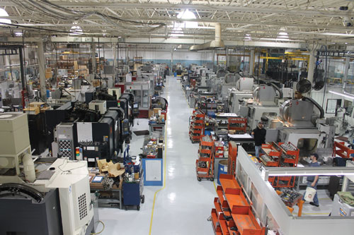
3-Dimensional Services Group was founded in 1992 with five employees. Today, more than 250 employees work on prototype and low-volume production in more than 200,000 square feet of manufacturing space. In 2005, the company expanded into the global market with a European office.
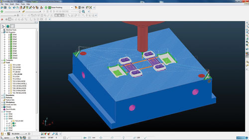
According to David Krajci, operations director at 3-Dimensional Services Group, Delcam’s intuitive PowerMill CNC programming software makes training easy. The CNC machinist was able to complete the CNC program for the plastic bushing in about 90 minutes.
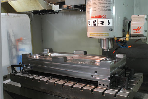
This Haas CNC VM3 machine is among a variety of machines the shop uses to produce molds. CNC operators, rather than a dedicated programmer, are responsible for programming the parts before they are machined.
Share


When an automobile OEM needed small plastic parts produced on an urgent basis, 3-Dimensional Services Group didn’t hesitate. As evidenced by the names of the three companies that comprise 3-Dimensional Services Group—3 Dimensional Services, Urgent Plastics Services and Urgent Design and MFG—the organization specializes in such timely work. Using CAD/CAM software from Delcam (Windsor, Ontario), the company was able to turn CAD data into validation parts in less than 24 hours, keeping the OEM from disrupting production.


All the companies in the group offer full-service engineering, design and rapid prototyping services. They specialize in producing prototype parts and limited production runs for military, automotive, medical, biomedical research and household appliance industries, among others. The group’s 200,000 square foot facility in Rochester Hills, Michigan, houses equipment for stereolithography, laminated object manufacturing, laser sintering, metal lamination, laser processing, waterjet, EDM, CNC machining, stamping, hydroforming and injection molding.
One particular project exemplifies how the group brings its individual company talents together to solve a customer’s problem. Just as a new automobile was about to launch, an auto OEM discovered a noise problem with the seat. Rather than delay production, engineers designed a small plastic bushing to damp the noise. After sending preliminary drawings, the OEM consulted with David Krajci, operations director at 3-Dimensional Services Group, about modifications required for successful injection molding. Upon receiving final CAD data at 3 p.m. on a Tuesday, a designer and mold maker worked to determine how many parts to produce with each shot, what mold base to use, where to gate the part and what actions, such as undercut holes, were needed in the mold.
After importing the OEM’s geometry into Delcam’s PowerShape CAD software, the mold designer established the die draw, orienting the geometry so that the mold would freely open and close. One way to think about the die draw is to consider, for example, molding a cup. The open end of the cup must be facing straight up so that the portion of the mold that forms the interior can be removed without interfering with the sides. Not only does the software identify interference, but it also helps identify areas in which draft needs to be added so the part could be removed from the mold easily, Mr. Krajci says. The next step was to define the parting line to help balance the mold. Using another PowerShape tool, the part was shaded with different colors to distinguish between the cavity and the core side of the parting line.
By 6 p.m., the designer and mold maker had made final adjustments and sent designs for each mold component—the core, cavity, insert, slide and core pin—to the CNC department for machining. CNC operators at 3-Dimensional Services Group are responsible for programming the parts before they machine them. “The guys running the machines have more understanding of what will work and what will not than CNC programmers sitting in an office,” Mr. Krajci says. “PowerMIll is very intuitive, so it is not difficult to train machinists to use the software,” he says.
He adds that the programmers appreciate the software’s wide range of machining strategies. For example, the latest release added a step cutting within area clearance strategy that helps increase material removal rates and reduce overall machining time. Modern roughing tools and large stepdowns can remove material quickly, yet the combination often results in leaving terraces on the part that must be removed by rest machining with a smaller tool. An alternative is stepping back up the terrace with the existing large tool, adding extra cuts at intermediate levels. This approach enables the same tool to remove more material within the same tool path. The material removal rate can be optimized by automatically increasing the feed rate as the depth of cut gets smaller.
With the machining strategies in place, the CNC operator picked a tool from the library and a stepdown value. The operator started with a large tool, and the software automatically determined which areas of the part it could cut. The operator then picked a smaller tool, and the software again showed which areas the tool could cut. To reduce machining time and avoid cutting where the tool was not needed, the software rapid traversed between the two areas. After finishing the program, the operator used the CNC software’s simulation module to compare the part to the original CAD geometry. It took about 90 minutes to complete the CNC program.
Setup for machining the mold took about four and a half hours. Then, the job was turned over to the night shift mold maker, who added waterlines and hand-finished the two halves to ensure proper mold closure. Completing these jobs and final mold assembly took two hours. The mold was then set up on the injection molding machine. The company uses quick-change molds, so all that had to be done was insert the slides into the frame, hook up the waterlines, pre-heat the mold, load the machine with material and start producing parts.
By noon on Wednesday, the company had shipped 100 validation parts to the OEM for testing. Quick turn-around and the ability to make the plastic bushing to spec won 3-Dimensional Services Group approval to produce 11,000 of the parts, for installation on early production vehicles to ensure that customers never experienced the noise.


Related Content

SolidCAM iMachining and Technology Wizard: Faster Machining and Longer Tool Life
Smarter toolpaths to tackle modern machining challenges.
Read More
Shop Reclaims 10,000 Square Feet with Inventory Management System
Intech Athens’ inventory management system, which includes vertical lift modules from Kardex Remstar and tool management software from ZOLLER, has saved the company time, space and money.
Read More
Can AI Replace Programmers? Writers Face a Similar Question
The answer is the same in both cases. Artificial intelligence performs sophisticated tasks, but falls short of delivering on the fullness of what the work entails.
Read More
Cutting Part Programming Times Through AI
CAM Assist cuts repetition from part programming — early users say it cuts tribal knowledge and could be a useful tool for training new programmers.
Read MoreRead Next

OEM Tour Video: Lean Manufacturing for Measurement and Metrology
How can a facility that requires manual work for some long-standing parts be made more efficient? Join us as we look inside The L. S. Starrett Company’s headquarters in Athol, Massachusetts, and see how this long-established OEM is updating its processes.
Read More