
Sophisticated Software for Solid Gear Design
Whether your computer platform is standalone or part of a suite, desktop or on the cloud, there’s a gear design package developed specifically to meet your needs.
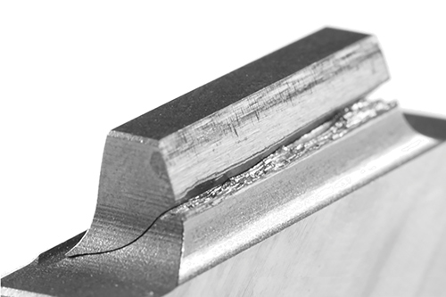
Flank fractures can cause a gear to fail. The flank fracture calculation according to ISO/DTR 19042 has been added to the latest KISSsoft release to minimize these types of crack formations in cylindrical gears and bevel gears.
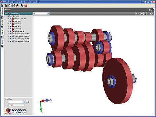
Concept from Romax Technology provides semi-automated sizing, definition and rating of gears, shafts and bearings. The software’s 3D visualization helps designers and engineers evaluate and optimize key design parameters quickly.
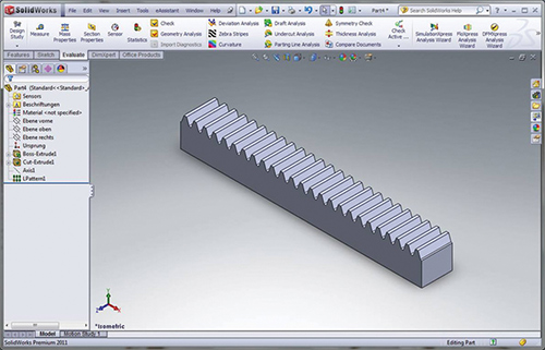
New eAssistant CAD plug-ins from GWJ Technology Autodesk Inventor, Solid Edge and SolidWorks (shown) let designers create 3D gear rack models in those CAD systems.
Share


If it’s mechanical and it moves, it probably has a gear inside. Gears are deceptively simple items, but not so simple to design—if the eventual goal is to have a long-lasting, efficient, vibration-free, quiet-running mechanical device.
Gears come in many different pair types, in all diameters and thicknesses, and they’re made of a variety of materials. They don’t even have to be circular.


Getting a handle on this variety in gears—what’s called designing and engineering—is crucial for the proper working of increasingly sophisticated and efficient moving machines, including electric and hybrid vehicles, wind turbines, consumer appliances, aerospace and defense, and so much more. “For the engineering teams tasked with developing new powertrains, resources are being pushed harder than ever and development processes are now very much under scrutiny,” say officials at U.K.-based Romax Technology. Gear design software provides so many benefits, continues Romax, including “more rapid gearbox concept modeling and analysis, fewer errors, improved processes, reduced rework, faster time to market, and lower overall development costs.”
Today, these benefits come not only from the features found in gear design software, but also from the availability of the software on so many different computer systems: standalone desktop, part of a desktop suite, online, and even software as a service.
Standalone Software
From the Swiss company KISSsoft AG comes the eponymous KISSsoft software for sizing machine elements (gears, shafts, bearings, connecting elements, springs, and both chains and belts). Sizing calculations are a function of individual parameters (profile offset, tolerances, wheelbase, etc.). For certain gears, the calculations can be quite extensive. For example, the calculation of the angular dimensions of bevel gears includes all the dimensions for creating the bevel gear drawing (tip and root circle diameters in the outer and inner bevel) and tooth thickness dimensions on the outer and inner bevel diameter for all types of bevel gears, including Klingelnberg and Gleason.
KISSsoft gets updated all the time, with the latest release dated March 2015. For instance, flank modifications used to be assessed in a contact analysis under load, which also accounted for mounting deviations and tooth deformations. In June, flank modifications were added to bevel gear designing. The resulting output includes the contact pattern, transmission error, stress distribution, and the risk of flank fracture. In March, reports from load spectra calculations became available for beveloid gears; these reports show the values for partial damage per load element. Moreover, the load and speed direction of each element can be considered separately. In January, a new algorithm was introduced for shaft calculations, yielding increased stability, better performance, and easier fault correction. The latest release also includes a variety of enhancements to the program’s 3D exports to common CAD packages, such as Autodesk Inventor 2016, Dassault Systèmes SolidWorks 2015, PTC Creo Parametric 3.0, and both Siemens PLM Software NX 10 and Solid Edge ST7.
Suite Success
The Concept software package from Romax is aimed at the conceptual stage of gearbox, transmission and driveline-system design. A related software product, RomaxDesigner, is a simulation tool for detailed analysis and optimizing drivetrains. Dynamic Fusion, a third product, creates dynamic models directly from Concept and RomaxDesigner for third-party multibody dynamics.
Concept has templates for non-gear experts to investigate gear designs, including durability, performance, noise and efficiency. These templates cover driveline and gearbox applications. The templates include gears, shafts, bearings, engine models, electric motor, wheels and multiple power loads. Software prompts using detailed parameters help in the design and analysis of gears. Expert designers can start fresh with a clean-sheet gear design.
Concept also includes various simulation tools, such as for predicting vehicle behavior and optimizing gearbox ratios. It has a bearing database and bearing selection tools for sizing and selecting bearings. Models created in Concept can produce unit-cost estimates, predict gear and bearing durability and provide early assessments of NVH performance.
The 2015 release of the software includes improved third-party CAD interoperability, including the ability to import complex 2D or 3D shapes such as planet carriers and differential cages. This version also has some new and improved components, such as detailed spline analysis and planetary modeling.
Web-based Design
eAssistant, from German-based GWJ Technology GmbH, is a web-based program for designing several machine elements (shafts, bearings, gears, springs and shaft-hub connections) in accordance with DIN and ISO standards and accepted literature. “Due to the web-based technology, the latest version is always available. No investment costs are required; updates and service packs are a thing of the past,” explain company officials. “Pay as you go; pay only for what you use.” The only system requirements are a Java-compatible web browser.
Cylindrical gear pair designs, for example, follow DIN 3960, 3961, 3964, 3967, 3977 and 868. The allowances for tooth thickness and center distance can come from a database or be defined individually. Additional chamfer can be part of the gear design calculation. Both full-depth teeth and stub-tooth gears are possible. Engineers can define flank modifications, such as end relief, and both symmetric and asymmetric lead crowning. Other features are available on request, such as the ability to design gears with helix angles greater than 45 degrees and with a non-integer number of teeth (i.e., number of teeth with decimal places). Finished geometries can be exported using eAssistant CAD plug-ins or the DXF interface.
When simulating geartooth forms in eAssistant, an engineer can choose whether to display the lower, middle, and upper allowances for the tooth thickness, the tip circle diameters, or center distance. The program displays hints and warnings as required, such as for meshing interferences.
In addition to the geometry calculation, eAssistant also calculates a gear’s load capacity (DIN 3990 Method B) to determine a gear's fatigue and static strength, as well as surface durability (pitting), tooth bending strength and scuffing load. Other factors affecting the working of a gear pair can be considered, such as base material, lubricants, grinding notches and operating modes.
Recent enhancements to eAssistant include a new module specifically for calculating rack-pinion gear pairs, which replaces using a cylindrical gear pair module. Two other modules were introduced for calculating the geometry of single cylindrical gears (external and internal). Also, there are new CAD plugins for Inventor, Solid Edge, and SolidWorks that support 3D gear rack modeling.
Downloadable Design
HyGears version 4.0 from Quebec-based Involute Simulation Softwares Inc. is a standalone program with “all the design, analysis, and manufacturing tools needed from idea to production,” according to Claude Gosselin, president of the company. Along with design capabilities for all sorts of gears, including zerol and coniflex, herringbone, and face-milled and cyclo-palloid spiral-bevel gears, this 3D engineering software can create five-axis CNC machining programs for cutting the gears on AB-, AC-, BA-, and BC-type CNC machines, using face mill, coniflex dish type, CoSIMT (spherical), end mill, or ball mill tools. HyGears can generate coordinate measuring machine (CMM) target files, as well as use CMM data to evaluate the quality of a gear, calculate corrective settings, or reverse engineer an unknown gear set.
“The initial design of a gear set requires very little data input as numerous default values can be computed as a starting point,” says Mr. Gosselin. Two functions in particular help out in the design, analysis and optimization of gear sets. Tooth contact analysis (TCA) provides the shape and location of the bearing pattern, ease off, and transmission error. Loaded tooth contact analysis (LTCA) calculates contact stresses, the extent of the bearing pattern, the transmission error and bending stresses to assess the gear’s behavior under load. Engineers can improve the initial designs at any time using specialized operators that can define each tooth flank independently. With the internal geometry editor, engineers can also modify blank geometry, cutter blade, and machine setting data. Modifications can also be made through advanced user-guided functions. At any time, HyGears can also produce a PDF-formatted summary of the gear design, including geometry, strength calculations, machine settings, TCA, LTCA, blank and worst-case graphic output.
Gear sets are displayed in WYSIWYG; simulations show the movements of cutting machines and tools. The program can run up to 20 combinations of torque, E, P, G and shaft and alignment angles, and display selected results graphically and as text.
While HyGears does not have an internal FEA solver, geometry created within the program can be exported as a standard Patran file. A built-in STEP interface provides direct export to most CAD and CAM systems.
Other advanced features include finite strips—a subset of the FEA that provides quick computation and display of bending stresses and deformations, providing the LTCA with very precise tooth stiffness for exact tooth load-sharing calculations—and an integrated contact element, which allows for the calculation of the contact stresses of any tooth geometry. Universal five-axis CNC output converts the machine settings of any face-milled spiral bevel and hypoid gear generator to X, Y, Z coordinates and B and C rotations, and spiral-bevel gear sets can be generated in which cutter tilt is not needed to achieve good bearing pattern and transmission error.
HyGears runs on Microsoft Windows XP or later.The most recent version of HyGears, build 404.50-457, has been available since June. HyGears is downloadable from the company website, and a demo version is valid for 15 days, with some features restricted.


Related Content

Faster Programming and Training Helps Automotive Shop Thrive
Features that save on training, programming and cycle times have enabled Speedway Motors to rapidly grow and mature its manufacturing arm.
Read More
Orthopedic Event Discusses Manufacturing Strategies
At the seminar, representatives from multiple companies discussed strategies for making orthopedic devices accurately and efficiently.
Read More
Advanced Tool Paths, Simple Implementation
Programming advanced tool paths used to be a complex, time-consuming task. Canned cycles in CAM software have now made them more accessible than ever.
Read More
The Power of Practical Demonstrations and Projects
Practical work has served Bridgerland Technical College both in preparing its current students for manufacturing jobs and in appealing to new generations of potential machinists.
Read MoreRead Next

OEM Tour Video: Lean Manufacturing for Measurement and Metrology
How can a facility that requires manual work for some long-standing parts be made more efficient? Join us as we look inside The L. S. Starrett Company’s headquarters in Athol, Massachusetts, and see how this long-established OEM is updating its processes.
Read More