
T Codes Simplify Tool Length Confirmation Process
CNC users can program custom macros and T codes to ensure cutting tools are the proper length for tool length compensation in machining centers.
.jpg;width=70;height=70;mode=crop;format=webp)
Share


Tool length compensation simplifies programming and enhances trial machining and sizing during setups and production runs. It also makes it possible to assemble and measure cutting tool lengths using an offline tool length measuring device.
Though tool length compensation is a good feature, it does have some drawbacks.


What are the drawbacks of tool length compensation?
1) The cutting tool must be rigid enough to machine using the programmed cutting conditions, and 2) the cutting tool must be long enough to reach the deepest machined surface without being so long that it collides with an obstruction during tool changes.
In some companies, programmers specify the components for assembling cutting tools along with a range of acceptable lengths.
Many companies, however, specify only the tool name and size, leaving it to the setup person to determine how to assemble cutting tools. Setup people may not know for sure whether each tool will have adequate rigidity, or whether its length is within an acceptable range.
While they may not be able to ensure rigidity, custom macros can solve the cutting tool length range question.
Basic Macro Setup
The technique here is especially helpful for machines with limited Z-axis travel, like small vertical machining centers and many horizontal machining centers. We are using FANUC custom macro system variables to access offset-related data, and our example also assumes the machine has FANUC’s standard set of six fixture offsets and the user plans to set the cutting tool length as the tool length compensation offset value.
Variables in the #2200 series provide access to tool length geometry offsets. Those in the #5200 series provide access to fixture offsets. Additionally, our example “second references” the related system variable values. Our test tool length values are:
#149=4.0
#2=#[2200+#149] (Current tool length)
With common variable #149 set to 4.0, the expression 2200+#149 renders 2204. The pound sign (#) outside of the brackets makes this system variable #2204, which accesses the value of tool length geometry offset number four. Similar techniques are used for accessing the currently instated fixture offset Z-register value. We are also using system variable #4014 to access the currently instated fixture offset value (54-59).
Consider the illustration.
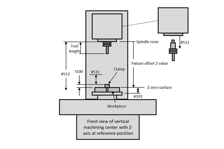
Input data comes from offsets, from system constants (#500 series permanent common variables) and from values specified within the program. The offsets include fixture offset Z values and tool lengths entered in the tool length compensation geometry offsets.
Users will only need to enter the following system constants one time:
#511: Clearance for making a tool change.
#512: Tool changer pullout amount (consult machine builder’s documentation).
#513: Z-axis travel (consult machine builder’s documentation).
These values match to the CNC program:
#100: Distance between Z-zero surface to highest obstruction (like a clamp).
#101: Distance between Z-zero surface and the deepest depth. This value can be specified prior to each tool change.
This technique operates from a user-defined T-code program. After setting a parameter (#6001, bit 5 for newer FANUC CNCs) to 1, any time the CNC sees a T code, it will store the T value in common variable #149 and execute program O9000.
There are two common styles of automatic tool changing systems.
What are the common styles of automatic tool changing systems?
With one, the T code by itself completes the tool change. With the other, the T code merely rotates the tool carousel, bringing the tool to the ready station while an M06 command changes the tools. The following example program should work nicely for both, though users may have to separate the T code and the M06 into two commands for the program to execute properly.
Sample Programs
Here are the programs. The main program (O6001) is abbreviated to show only the related commands:
O6001 (Main program)
G54 (Select fixture offset)
#100=2.0 (Height of tallest feature/obstruction from fixture offset Z-zero surface)
#101=2.5 (Deepest depth of machining for tool 4)
(.)
(Program startup commands)
(.)
T04 (Calls program O9000, the user-defined T-code custom macro)
M06 (Tool change will occur if tool is within range)
(.)
(Machining with tool station 4)
(.)
#101=1.0 (Deepest depth of machining for tool 5)
(Tool startup commands)
(.)
T5 (Calls user-defined T-code custom macro)
M06 (Tool change will occur if tool is within range)
(Machining with tool 5)
(.)
(Balance of machining program)
(.)
M30
O9000 (Tool checking custom macro)
#1=ABS[#[5203+[#4014-53]*20]] (Current fixture offset Z value)
#2=#[2200+#149] (Current tool length)
IF[[#1-#2-#511-#512-#100]GT0]GOTO5 (Is the tool length okay?)
#3000=100(TOOL IS TOO LONG)
N5#3=#1+#101 (Deepest depth)
#4=#513+#2 (Tool reach)
IF[[#4-#3]GT0]GOTO10 (Will the tool reach deepest surface?)
#3000=101(TOOL TOO SHORT)
N10T#149 (Rotate tool to ready position)
M99


Related Content

Continuous Improvement and New Functionality Are the Name of the Game
Mastercam 2025 incorporates big advancements and small — all based on customer feedback and the company’s commitment to keeping its signature product best in class.
Read More
Setting Up the Building Blocks for a Digital Factory
Woodward Inc. spent over a year developing an API to connect machines to its digital factory. Caron Engineering’s MiConnect has cut most of this process while also granting the shop greater access to machine information.
Read More
Advanced Tool Paths, Simple Implementation
Programming advanced tool paths used to be a complex, time-consuming task. Canned cycles in CAM software have now made them more accessible than ever.
Read More
How I Made It: Mike Lynch
Mike Lynch has been a CNC programming teacher for three decades, in addition to being the longest-running columnist in Modern Machine Shop history, providing generations of machinists with expert insight into the art of programming parts. With this issue being Mike’s last, we wanted to highlight his career and what it means for the industry.
Read MoreRead Next

How To Reference Custom Macro Variables by Name
FANUC now enables CNC users to reference custom macro system variables by names in addition to hard-to-remember numbers. Here’s how.
Read More
5 Tips for Selecting the Optimal Spindle Range
Learn how to select the appropriate spindle range and ensure that your CNC machining center or turning center is running an optimized cycle.
Read More