
The Fast Track To High Speed Drilling
Drill more productively by making a few strategic changes to the process. Those same changes may also let you drill dry.
Share


Through-the-tool coolant ducts apply coolant where it is needed, at the tip of the drill. At very high cutting speeds, high-pressure internal coolant may be essential for flushing the hot chip out of the hole.
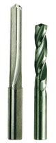
For short-chipping materials like cast iron, a straight-flute drill (far left) may offer the most effective route for ejecting the hot chip from the hole.
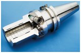
The toolholder clamp generally accounts for most of the total runout measured at the cutting edge of the drill. The graph (above, left) shows the effect of this runout on the average life of a drill made from conventional carbide, and from a carbide grade engineered for more toughness. The photo (above, right) shows a cutaway view of a hydraulic toolholder, which uses a reservoir of oil to equalize clamping pressure all around the tool. This type of toolholder is recommended equipment for high speed drilling. (Photo courtesy of Kennametal)
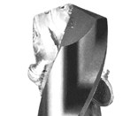
Built-up edge is a danger where there is built-up heat. If a hot chip "smears" against the tool's surface, it can adhere there, maybe leading to a catastrophic failure.
The toolholder clamp generally accounts for most of the total runout measured at the cutting edge of the drill. The graph (above, left) shows the effect of this runout on the average life of a drill made from conventional carbide, and from a carbide grade engineered for more toughness. The photo (above, right) shows a cutaway view of a hydraulic toolholder, which uses a reservoir of oil to equalize clamping pressure all around the tool. This type of toolholder is recommended equipment for high speed drilling. (Photo courtesy of Kennametal)
Smaller-grain carbides deliver improved resistance to chipping (toughness) with little change in wear resistance (hardness).
A carbide edge removes material through an advanced fracture mechanism. It dislodges material well ahead of the edge's path. This characteristic makes it easier to protect a carbide cutting edge from the hot chip.
Ceramic drills combine the benefits of high speed drilling and drilling dry in the machining of cast iron.
With milling, at least there is some room for maneuvering. Part of any speed increase can be devoted to taking lighter and more numerous cuts, relaxing the strain on the overall process.
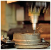
Not so with drilling. Whether a given drill is run at conventional speed or "high speed," one pass still equals one hole. Fast or slow, the tool path is the same. This is why any challenges inherent in the slower process grow more pronounced as spindle speed and feed rate are increased. Chief among these challenges is how to remove heat and chips as the tool feeds deeper into the hole.


Cutting tool maker Guhring, Inc. (Brookfield, Wisconsin) has studied the drilling process. The company often advises customers in how to construct their own processes to achieve high speed drilling. Here, the term has a specific definition. Guhring uses "high speed drilling" to refer to drilling at spindle speeds high enough to permit penetration rates of three to ten times the conventional rate, as dictated by the workpiece material.
However, the strategies the company applies could also be used to achieve high speed drilling according to a broader and more accessible definition: drilling faster than before. If the machine tool offers spindle speed and feed rate currently going unused in drilling operations, then it may be possible to realize the same tool life and tool performance as today at higher rates of penetration, just by making the right changes to other components of the process. By choosing the appropriate toolholder, drill, coating, and coolant delivery system, the shop may be able to unlock potential productivity that has so far gone untapped.
This article presents some of what Guhring has learned about how to drill faster. Sources include company senior design engineer Milan Petrovic, and the findings of Dr. Tibor Cselle, the com-pany's director of R&D.
Nearly all of the suggestions in this article might apply to the drilling process at any speed. However, they take on a new importance as speed increases beyond conventional values. Any process component worthy of attention at conventional speeds will likely merit more attention—and more investment—as speeds increase.
This is particularly true of coolant. Through-the-spindle coolant, coupled with drills offering internal ducts for delivering the coolant directly to the tip of the tool, can extend drill life at almost any speed. However, in most high speed drilling applications today, a flow of high pressure coolant through the tool is critical for removing potentially catastrophic chips and heat.
Tomorrow, that may change. A few companies in the United States are experimenting with reducing the demand for coolant in high speed drilling. They are following the lead of European manufacturers facing much higher costs to dispose of used coolant. In parts of Europe—and maybe in the United States—high speed machining will increasingly be applied with minimal coolant, or with none at all.
Any shop implementing high speed drilling is also positioning itself to drill dry in this way, whether or not that position is an attractive one today. High speed drilling and dry drilling are complementary processes presenting similar engineering challenges. Thus, by adopting some of the techniques for high speed drilling found in this article, a shop can also be preparing itself for the transition to a machining process with a much smaller appetite for coolant.
The Concentric System
One of the most important requirements for high speed drilling is also one of the most basic. Any skilled machinist knows to check the concentricity error—or runout—at the cutting edge of the drill. As speed increases, it becomes even more important for the center line of the drill to be on target.
A key reason why has to do with tool material. At lower speeds, shops can drill effectively with tools made from high speed steel, which offers relatively high toughness and bending strength. However, higher speed applications demand carbide, or possibly ceramic—both of which sacrifice some of this toughness in favor of wear and heat resistance at higher cutting speeds. The evenly distributed cutting forces resulting from low runout can be essential for achieving an acceptable tool life with these brittle materials, particularly as the spindle rpm is pushed into the five-figure range.
An effective process for drilling at this speed should have a total runout of no more than 20 microns, says Guhring's Mr. Petrovic. This error, measured after the drill has been loaded into the toolholder and spindle, is the sum of the runout in four components of the process: the machine spindle + the spindle/toolholder interface + the toolholder/tool interface + the tool itself. If the shop uses an existing machine for high speed drilling, and has no plans to replace the spindle, then the first two of these contributors to the error are beyond control. However, neither one of these is likely to be the most significant source of runout on a relatively new machine. The spindles offered for most of today's machine tools, even relatively inexpensive ones, typically offer concentricity and toolholder location tolerances sufficient to leave ample room in this 20-micron margin. Nor is the drill itself likely to contribute much to that error. Cutting tools today are being manufactured to ever-tighter concentricity tolerances.
That leaves the toolholder clamp as the most significant source of runout. In fact, the wrong toolholder may account for more than 20 microns of error by itself. Guhring researchers have sampled numerous standard collet and side-lock toolholders, and discovered a wide range of clamping concentricity from vendor to vendor. In general, they concluded that the highest quality side-lock toolholder can hold runout error to about 8 microns, the highest quality collet chuck can hold it to about 11 microns, but that some varieties of both types may add 30 microns to the total error. A third alternative—and the one that Guhring typically recommends—is the hydraulic chuck, which uses a reservoir of oil to equalize clamping pressure all around the tool. The company has found these toolholders able to deliver repeatable clamping concentricity ranging from 3 to 9 microns.
If the shop does have the luxury of selecting a spindle for high speed drilling, Mr. Petrovic recommends that the toolholder interface be HSK. The HSK connection offers a small, predictable runout error. "Around 12 to 15,000 rpm, there comes a point where HSK is a necessity for getting the most life out of the drill," Mr. Petrovic says.
Tool Material
An inevitable consequence of drilling faster is faster wear on the cutting edges. A likely consequence is more heat in the cutting zone.
This is why any tool used for high speed drilling must be chosen not just for its hardness—which determines resistance to wear—but also for the extent to which it keeps its hardness at high temperatures. Both requirements tend to disqualify high speed steel tooling. Instead, the vast majority of today's high speed drilling applications call for a tool made from solid tungsten carbide, in some high temperature grade.
The tool's heat resistance becomes more important as the holes get deeper. For relatively shallow holes, on the other hand, the high speed tool move itself may help avoid some of the heat buildup. Think of this shallow drill move like a karate chop. If the shop can drill a hole effectively at higher spindle speed, it may be possible to increase the feed rate proportionally. One result of the increased "ipm" is a shorter engagement time. The tool dips in and out of a shallow hole quickly, so less of the energy of the process is diverted into heat. Thus, a high speed drilling move's ability to avoid heat can be compared to a blow that breaks a board quickly enough to avoid a broken hand.
However, as hole depth grows to even a few diameters, this depth reaches the point where even a high speed move cannot avoid heat buildup. Here the tool's ability to resist the ill effects of this heat becomes critical.
There are tool materials that deliver better high temperature hardness than carbide. Notable among these is ceramic. However, relatively few shops today possess machine tools delivering the speed and rigidity necessary to take best advantage of these drills. That may change. To the extent that drilling dry gains acceptance in the future, more and more shops will be adopting these tools.
Tool materials showing even better resistance to wear are polycrystalline diamond (PCD), which is appropriate for nonferrous materials, and cubic boron nitride (CBN), which is appropriate for steel. However, these materials are expensive. In addition, their low toughness leaves them vulnerable to cracking as a result of vibration or thermal shock. Like ceramic, these materials also tend to demand a high performance machine tool unlike the ones found in the typical shop. That is why the appropriate choice for almost any existing drilling application—at least for now—is likely to be carbide.
What about tools with steel bodies and brazed-on carbide tips? These are sometimes used for conventional-speed drilling on older machines, and in other circumstances where rigidity is relatively poor. Where chatter is a danger, a steel body—more flexible than a solid carbide one—is more likely to yield to protect the cutting edges from chipping. However, the same brazed tool probably will not work in a high speed application. The higher temperatures tend to soften the braze that holds the carbide tip in place.
Instead, where chatter is a danger in high speed drilling, a better choice is to switch to a finer grain carbide. Cutting tool manufacturers today offer carbide grades with grain sizes on the order of 0.5 micron or smaller, compared to the more standard 2.5 microns. Smaller carbide grains produce tools less likely to chip, with little or no loss in hardness. Thus, carbide tools with smaller grains achieve the wear resistance that makes carbide attractive, but make less of a sacrifice in toughness to realize this.
Coating
The right choice of coating can extend the life of the carbide tool considerably by offering an additional line of defense against both the friction and the heat of a high-rpm process. Three coatings commonly used in high speed drilling are:
- Titanium aluminum nitride (TiAlN). This coating is effective on cast iron and other abrasive materials. It also serves as an excellent insulator for operations characterized by high temperatures, including dry machining.
- Titanium carbon nitride (TiCN). This is a thicker, multi-layer coating that guards the tool against wear, particularly when machining steel. One drawback to this more complex coating is that it cannot be reapplied. Tools coated once with TiCN typically are recoated with TiN.
- Titanium nitride (TiN). This coating is less expensive than the previous two. Though TiN cannot match the performance of the previous two coatings in their ideal applications, the strengths of TiN are that it is generally cost-effective and universally applicable. This makes the TiN-coated drill a good general purpose tool in any shop machining a variety of materials.
Proprietary coating formulas designed for high speed drilling may eclipse the performance gains of these more standard choices. For example, Guhring claims that one formula it recently introduced can deliver performance benefits equivalent to all of the coatings above.
Flute Geometry
A common metalworking drill design has flutes winding up the shank of the tool in a helix that forms a 30- or 40-degree angle with the center line of the drill. The channels between these flutes form a conveyor for lifting chips away from the cut and out of the hole. As the drill turns, the flutes wedge the chips up like a turning screw. This largely mechanical process leaves the chip repeatedly—if not continuously—in contact with the tool.
High speed drilling demands a different approach. A high speed drilling process should aim to prevent the chip from coming into contact with the tool's cutting edges, and minimize chip contact with the flutes.
Again, the danger is heat. At the highest cutting speeds, the chip is likely to be so softened by heat that it will "smear" against the tool, and adhere there by filling in microscopic crevices in the tool's surface. If so, the geometry of the cut will change, as the built-up edge becomes a new cutting surface. This may force the tool off-center, and this in turn may well lead to failure.
Completely isolating the chip from the tool is impossible. However, with a carbide tool, it is quite possible to separate the chip from the cutting edge. A carbide edge does not really "cut"—at least, not the way a high speed steel edge does. Instead, the honed carbide edge removes material through the mechanism of advanced fracture. Splitting material ahead of its path like a blunt wedge, this edge dislodges the chip well in advance of the tool's path (see illustration at right).
From there, the goal in high speed drilling should be to keep the chip away. High pressure coolant, delivered through internal ducts and out the tool tip, can be an effective tool for accomplishing this.
But when the flow of through-the-tool coolant acts to drive the chip, the tool is no longer well served by a relatively long helical channel along its length. Instead, the tool needs to provide a more direct route by which the coolant flow can eject the chip.
When drilling aluminum and steel, Mr. Petrovic says, "Some spiral is still needed." Recent tests with drilling aluminum at speeds of 10,000 rpm and higher suggest that a slower spiral of 15 degrees from the center line is the most effective conduit.
However, in short-chipping materials—most notably cast iron—the zero-degree spiral is the right choice. That is, a straight flute. For a short chip, the shortest route from cut to ejection is a straight line. The only requirement is that the coolant pressure be strong enough to drive this chip up and out of the hole.
Coolant Delivery
Through-the-tool coolant ducts apply the coolant's ability to remove heat and chips very close to where it is needed, at the tip of the carbide tool. Drilling tests in steel over a range of speeds show that through-the-tool coolant improves tool life over external coolant at almost any depth. This, despite the loss in rigidity that comes from adding internal ducts to an otherwise solid tool. At depths of three diameters, the net tool life gain from internal coolant averages about 20 percent. At depths of five diameters, the difference is more like 40 percent, and only grows more pronounced as the holes grow deeper than this.
The coolant demands of high speed drilling may call for retrofitting a higher pressure pump and coolant delivery system than the one that came standard on the machine tool. Mr. Petrovic sees 750 psi as a minimum pressure for high speed drilling of short-chipping materials. Applications in steel, or most varieties of aluminum, likely will call for pressure in excess of 1,000 psi.
One consequence of this is that drilling faster can demand significantly more coolant, and therefore more coolant-related costs. Shops have to pay more to purchase new coolant, and more to dispose of used coolant and coolant-soaked metal fines. A more economical approach may be to machine with no coolant, or with an amount that is economically negligible.
Drilling Dry: The Next Step?
Dry machining is a practice apart from high speed machining. In parts of the world where the cost of coolant disposal is high enough, some manufacturers find it cost-effective to sacrifice some of the speed and productivity they might enjoy if coolant were cheaper.
However, dry machining and high speed machining complement one another. Any shop that has achieved some degree of high speed machining has already tackled a key challenge to machining dry: how to protect the tool from heat. In fact, for shallow holes, a dry process may run better at a high feed rate, because the short engagement time may limit heat buildup. High speed drilling may make up for any losses incurred by drilling dry. If a given dry machining operation does require a reduced cutting speed, then changing the process to make it conducive to faster drilling may be sufficient to win back some lost productivity.
Should you be thinking about drilling dry, or about dry machining in general? In Germany, costs directly related to coolant purchase, management, and disposal account for 16 percent of the annual costs to that country's metalworking industry. There is no evidence to suggest that American metalworkers spend near that much money for their coolant, but individual shops might depart from the average considerably. If your own coolant costs are already very high, or if you believe the United States will follow the lead of other industrial nations in making coolant more costly to handle, then it may be worthwhile to determine what dry machining can achieve in your application.
At present, dry machining's effectiveness varies considerably from metal to metal. The metal most appropriate for machining dry appears to be cast iron. Here, a ceramic drill may be an attractive option. Ceramic tooling retains its hardness at high temperatures, and runs completely without coolant or lubricant. Furthermore, the life of ceramic tooling often increases as cutting speed increases. However, this leads to one limitation of a ceramic drill. This tool actually requires the higher speed in order to achieve enough tool life to make it cost-effective. As a rule of thumb, ceramic drills must be run at a speed of at least 650 sfm.
Another limitation of this tool material is brittleness. Ceramic drills can be used only where the material will collapse into small and easily manageable chips. This essentially limits the tool to cast iron, and even then the tool is generally far more effective in holes no more than about four diameters deep. The brittleness also demands attention to the overall process beyond what a carbide drill would require. Total runout at the cutting edge should be held to within just 10 microns to ensure sufficiently balanced cutting forces. This will tend to require a high quality spindle, in addition to a hydraulic toolholder. A ceramic drill also may demand a high performance machine tool—one featuring axis drives able to hold a position vibration-free while the drill is in the cut.
These limitations make carbide the more widely applicable tool material, even for drilling dry. Some toolmakers offer carbide grades specifically engineered for dry machining. The carbide tool can be coated with TiAlN, or any proprietary coating that offers even better insulation for the tool. The same tool also can receive a coating to improve its chip transport characteristics (see "Soft lubricating coating" below in "Just Add Lubricity"). And while the resulting drill can't match the performance of a ceramic drill on a high performance machine tool, it can deliver respectable tool life—at a much lower cost per tool—in a dry drilling process where the speed, concentricity, and/or rigidity is slightly less than what a ceramic tool would mandate. Plus, the coated carbide tool is an appropriate choice for dry machining of not just cast iron, but also steel or aluminum.
Even so, the carbide tool that performed so well with a flow of high pressure coolant may fail to perform effectively when that coolant is removed. The tool may stand up to the heat, but some other component of the process has to replace at least some of the chip removal benefits the coolant stream once provided. The key is to grease the path for better chip removal without coolant. This may not be an expensive proposition.
Just Add Lubricity
In the same way that relatively small investments can enable an existing drilling process to run faster, a low-cost add-on can enable an existing process to run effectively dry—or nearly dry. Options include:
- Soft lubricating coating. A coating designed only for chip transport, to keep the hot chip from adhering to the tool, can be applied over the tool's heat-resistant hard coating. With no high pressure coolant to flush out the chip, the mechanical action of the slowly spiraling flutes once again becomes the mechanism of chip evacuation. A soft coating can provide a nonstick surface that keeps the chip moving along this conveyor, all the way up the tool and out the hole.
- External minimal lubrication. A process using this option—or the internal version below—would be better described as "quasi-dry" drilling. Neat oil, or some other lubricant, can be applied to a process in quantities of only half a gallon per shift. The key is a dual nozzle operating according to the Venturi principle. An inner nozzle delivers a fine stream of the lubricant, while an outer nozzle surrounds this with a jet of air to contain the lubricant and carry it to the tool (see illustration of external minimal lubrication). This nozzle is positioned less than an inch away from the tool, where (with luck) it may be able to keep the drill lubricated enough to keep the chips sliding along.
- Internal minimal lubrication. A similar minimal lubricant can be delivered through a tool with internal ducts. Guhring has developed a low cost mechanism for accomplishing this: a toolholder with both a compressed air pump and a reservoir of lubricant built into its body. The rotary motion of the spindle drives the pump, sending an aerosol mixture of lubricant out through the tip of the tool (see illustration of internal minimal lubrication).
Other, more expensive technologies can help the shop that has made a commitment to drilling dry. These include chip suction systems; more efficient through-the-spindle systems for delivering minimal lubrication; and even machine tools able to drill up into the workpiece, so gravity helps clear the chips away.
But it is the lower cost "dry" technologies that are arguably more significant today. These options give dry drilling one more characteristic in common with high speed drilling. Today, both processes are accessible. They are within reach of almost any shop—including one that has little money to spend on changing the way it currently drills its holes.


Related Content

Finding the Right Tools for a Turning Shop
Xcelicut is a startup shop that has grown thanks to the right machines, cutting tools, grants and other resources.
Read More
Shop Reclaims 10,000 Square Feet with Inventory Management System
Intech Athens’ inventory management system, which includes vertical lift modules from Kardex Remstar and tool management software from ZOLLER, has saved the company time, space and money.
Read More
Orthopedic Event Discusses Manufacturing Strategies
At the seminar, representatives from multiple companies discussed strategies for making orthopedic devices accurately and efficiently.
Read More
10 Robotic Solutions You Can Find at IMTS 2026
Discover how today’s robots and cobots are making it easier than ever to automate tasks, free up skilled workers, and run machines unattended – even in small and midsized shops.
Read MoreRead Next

OEM Tour Video: Lean Manufacturing for Measurement and Metrology
How can a facility that requires manual work for some long-standing parts be made more efficient? Join us as we look inside The L. S. Starrett Company’s headquarters in Athol, Massachusetts, and see how this long-established OEM is updating its processes.
Read More