
Can My Machine Tool Access My Support Structures?
Analyzing the machinability of support structures opens a new way of thinking about optimal build orientation.

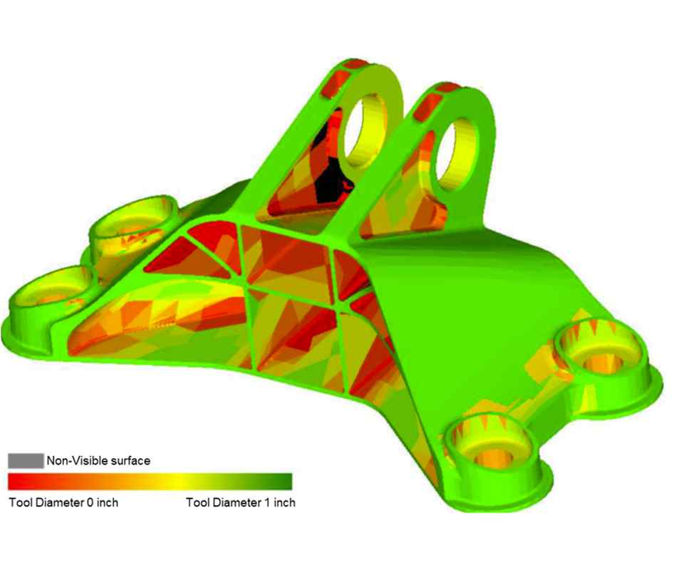
Figure 1: Tool accessibility map for CE engine bracket that was offered as a design challenge on GrabCAD.com.
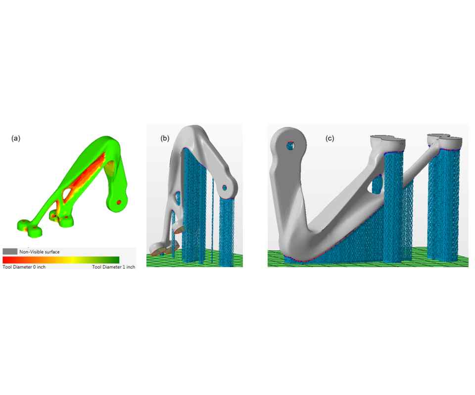
Figure 2: (a) Tool accessibility map for GrabCAD.com/Alcoa bracket, (b) optimal orientation for support machinability and (c) optimal orientation to minimize distortion.


Support structures are a pain for metal parts additively manufactured with laser powder-bed fusion. As much as you would like to redesign or orient your part in a way that avoids needing support structures altogether, invariably, you are going to have deal with them at some point. Wouldn’t it be nice to know how easy they are to access for machining and finishing operations? It would also be nice to know if your available machine tools are not going to be able to access them through that intricate geometry that you are additively manufacturing.
Luckily, I had the good fortune of reconnecting with Dr. Matthew Frank, a Penn State alumni who is now an associate professor at Iowa State University. Dr. Frank’s graduate work focused on using CNC machining for rapid prototyping, specifically, automating subtractive manufacturing processes to compete directly with additive manufacturing. You can find several of his papers online (for example, “Rapid Planning for CNC Machining” and “Subtractive Rapid Prototyping”), but that is not what I want to share this month. It is how he and Dr. Niechen Chen, his former PhD student who is now an assistant professor at Northern Illinois University, adapted those algorithms to analyze the machinability of support structures for AM parts. As you might guess, this opens a whole new way of thinking about optimal build orientation.


Finding the best build orientation for an additively manufactured metal part requires resolving the tradeoffs between build time, support structures, thermal distortion and many other competing objectives. Minimizing build time requires minimizing build height, but this will often lead to excessive overhangs and extensive support structures. Minimizing support structures is certainly desirable, but without sufficient supports, the part may warp as it is built, which can lead to a build failure. Finally, minimizing thermal distortion requires extensive computational analysis to find the best build orientation, and many times extensive support structures are required to reduce distortion.
With Dr. Frank and his research team’s latest work, we can now quickly analyze the accessibility, and hence the machinability, of support structures in all of these possible build orientations and use that information to help decide the best way to orient the part. To accomplish this, Dr. Frank combines ray-tracing algorithms and visibility analysis to determine whether a surface of the part can be accessed by a tool of a given size or shape. His software reads in an STL file and analyzes whether each triangle is visible to the “rays” that are projected and whether they are accessible. The diameter of the ray corresponds to the size of the tool, and the offset of each triangle from the outer boundary correlates to the cutting depth of the tool.
By performing this analysis for a set of cutting tools, you can quickly generate what Dr. Frank calls a tool accessibility map. Figure 1 shows an example for the GE engine bracket that was offered in a design challenge on GrabCAD.com. The color mapping in the figure shows what can be accessed by the available machine tools, with green being easy to access and red requiring smaller tools or limited access. Areas in gray indicate regions that are not visible and, therefore, cannot be accessed by a machine tool.
This information is helpful for build-orientation analysis. Figure 2 shows the a design from the Alcoa airplane bearing bracket challenge organized by GrabCAD.com. You can see in the figure how different the recommended build orientations are if you want to minimize thermal distortion or maximize machinability of support structures.
For novice designers and those new to AM, analysis tools like this are important to help identify the impacts of different build orientations. Granted, you may still encounter issues machining the support structures themselves (see my August 2018 column), but at least you will know whether you can access them in your intricate AM geometry.
For more information about this tool accessibility and machinability analysis algorithm, feel free to contact Dr. Matthew Frank directly at mfrank@iastate.edu.


Related Content

Digital Thread Enables First-Time-Right 3D Printing
Connecting all stages of manufacturing, from design to postprocessing, helps break down barriers to industrializing additive manufacturing.
Read More
In Moldmaking, Mantle Process Addresses Lead Time and Talent Pool
A new process delivered through what looks like a standard machining center promises to streamline machining of injection mold cores and cavities and even answer the declining availability of toolmakers.
Read More
4 Ways 3D Printing Is Changing Medical Implants
Additive manufacturing provides new ways of making medical implants, but its impact is greater than this. How 3D printing is changing medical manufacturing and improving patient outcomes.
Read More
How Automation Keeps Quality Control in Control
Collaborative robots help inspection keep pace with machining in a custom, digitalized workflow for complex aerospace and defense parts.
Read MoreRead Next

The Cut Scene: The Finer Details of Large-Format Machining
Small details and features can have an outsized impact on large parts, such as Barbco’s collapsible utility drill head.
Read More
3 Mistakes That Cause CNC Programs to Fail
Despite enhancements to manufacturing technology, there are still issues today that can cause programs to fail. These failures can cause lost time, scrapped parts, damaged machines and even injured operators.
Read More
