
An Alternate Route For Generating An Alternate Tool Path
A universal toolpath engine for roughing pockets optimizes cycle times by maintaining a constant material removal rate regardless of part geometry. This toolpath engine is not a CAM system. Instead, users pay a monthly fee to upload geometries to a secure Internet server and quickly receive tool paths that can be used with any CAM system.


Because the tool on the left is fully engaged with the material at full depth of cut, material removal rate increases as does stress on the tool. By keeping the material removal rate constant, the alternate tool path on the right automatically reduces the depth of cut to maintain the desired removal rate.
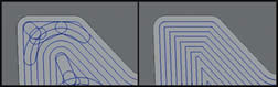
The traditional tool path on the right contains sharp corners that cause spikes in tool load. A new toolpath strategy shown on the left maintains a constant rate of material removal. It has smooth curves and consistent load on the tool.

Because the tool on the left is fully engaged with the material at full depth of cut, material removal rate increases as does stress on the tool. By keeping the material removal rate constant, the alternate tool path on the right automatically reduces the depth of cut to maintain the desired removal rate.
Share


CAM programmers make important decisions when the time comes to generate tool paths. Resident in the various CAM systems are a number of different toolpath generation engines from which they can choose. Their challenge is to pick the strategy and cutting parameters that will machine a given geometry in the shortest cycle time while limiting tool wear. Their decision is based on experience and knowledge of their machine tool’s capabilities.
Because many of these toolpath strategies are driven by the part’s boundary geometry, they sometimes direct the tool into corners or slotting cuts that cause the material removal rate (and the load on the tool) to increase. To reduce the chance for premature tool wear or breakage in these conditions, programmers may apply modest cutting parameters that result in extended cycle times. They might also use feed-rate optimizers that post-process the tool path and adjust feed rates downward when a large amount of material is detected. This latter reactionary method requires considerable setup and data entry for programmers because a number of machining factors must be considered for the optimizer to work effectively.


Glenn Coleman says what had been lacking was a universal toolpath algorithm that not only worked effectively for any part, but also allowed programmers to specify aggressive cutting parameters without overloading the tool. Mr. Coleman is the chief product officer for Celeritive Technologies (Cave Creek, Arizona), a company that says it has developed such a universal toolpath strategy for two-axis roughing routines. What makes its VoluMill toolpath engine fundamentally different from other strategies is not only its proprietary toolpath algorithm, but the way users access and use the algorithm.
A VoluMill tool path maintains a near-constant volumetric rate of material removal throughout the cut. It does this using a true constant stepover, planning the tool path so it contains no sharp corners and automatically manipulating feed rate and/or axial depth of cut to maintain a given material removal rate. Therefore, when tool engagement increases, the tool does not experience the load spikes typical of other toolpath strategies. The consistent tool load enables the use of more aggressive cutting parameters, regardless of the boundary geometry, which can significantly reduce cycle times.
VoluMill isn’t a CAM package, however. Instead, the toolpath engine is available as a Web-based, client/server platform that is suitable for use with any CAM system. Tool paths are generated by using the client to upload part geometry and cutting parameters to a secure Internet server that calculates the tool path and returns it to the programmer in a matter of seconds. Users enroll in a monthly or annual VoluMill service plan, which gives them unlimited access to create any number of tool paths. Service plans are currently available starting at $95 per month.
Terry Sorensen, Celeritive’s president, realizes this is unconventional. However, he believes users will come to appreciate the flexibility that the client/server platform offers because programmers can continue using their CAM system of choice. “Offering VoluMill as a toolpath service means users pay for only what they need, and they can easily add or remove licenses at any time to adapt to changing business conditions,” Mr. Sorensen says. “VoluMill technology is constantly evolving, but we can quickly and remotely make updates or resolve any user issues without requiring users to install new software or wait on a new software release.”
Constant Material Removal Rate
For a given tool and workpiece material, users can first determine the straight-line toolpath parameters—feed rate, spindle speed, stepover and axial depth of cut—that offer the best tool life and material removal rate. VoluMill tool paths can then be safely run using those parameters regardless of part geometry or number of pocket islands. The resulting tool path might look different and possibly can be longer than a conventional tool path. However, the VoluMill tool path can still deliver a faster cycle time by maintaining the heftiest cutting parameters possible throughout the cut. (Table 1 contains results of comparison test cuts.) In fact, Mr. Coleman says some tests showed it is possible to cut several times faster than a cutting tool’s recommended chip load because the tool is not subjected to spikes in material removal rate.
VoluMill is not a trochoidal tool path. Trochoidal tool paths use looping motions in an attempt to avoid burying the tool. This results in a longer tool path and cycle time, Mr. Coleman says. Conversely, a constant-stepover VoluMill toolpath is designed so that the tool won’t be buried, except in carefully planned and controlled conditions, thus eliminating the need for the circular motion.
Parameter Traditional Tool Path VoluMill Tool Path Benefit
Cycle Time 98 seconds 50 seconds Shorter Cycle Time
Feed Rate 200 ipm 500 ipm Faster Feed Rate
Spindle Speed 8,000 rpm 12,000 rpm Higher Spindle Speed
Spindle Load Spikes over 100% Always less than 90% Reduced Spindle Strain
Stepover 40% 75% Larger Stepover
Depth Of Cut 0.250 inch 0.500 inch Deeper D.O.C.
Passes 2 1 Fewer Passes
Table 1. Here are the results of a comparison test performed by GateWay Community College, located in Phoenix, Arizona. The machine tool used was a Haas VF3 with an OSG 0.5-inch, three-flute flat end mill cutting 6061-T6 aluminum.
VoluMill does not plunge a tool into the workpiece to begin a cut. Rather, it ramps the tool downward not only to reach the total depth of cut, but to create an open space that serves as a transition area. Every time the tool transitions from the end of one cut into another, it does so in this original transition area or another one created to avoid shocking the tool. The toolpath engine allows users to specify a high feed rate specifically for instances when the tool traverses these previously cut areas. In addition, a reposition clearance lifts the tool slightly above the machined floor so it isn’t dragged across the floor. In situations where a tool must be driven in a full slotting movement, the axial depth of cut will be automatically reduced to maintain a constant material removal rate.
Using The Client To Generate A Tool Path
Depending on the CAM system, programmers generate a VoluMill tool path using either a universal client or a dedicated client that is integrated directly into the CAM system. Currently Celeritive offers a dedicated VoluMill client for CNC Software’s Mastercam and is working with other CAM software companies to develop dedicated clients for their systems. In Mastercam, the VoluMill client appears as an addition to the other eight toolpath options. Additionally, the cutting parameter dialog box is designed to look nearly identical to the other toolpath engine dialog boxes, and users create a VoluMill tool path just as they would for any of those.
Once the programmer inputs the machining parameters and clicks to generate a VoluMill tool path, the client sends an HTTP request (just like a Web browser) to the VoluMill server. This request contains the programmer’s user name and password, part geometry and cutting parameters. The server calculates and returns the tool path to the user in a matter of seconds. The resulting tool path can then be backplotted, verified, modified and posted like any other tool path generated in the CAM system.
The universal client functions a bit differently. Programmers export a .dxf file from their CAD or CAM system and then use the universal client to browse for that file. After uploading the cutting parameters and .dxf file to the server, VoluMill returns G code that users can modify as needed and then cut and paste into an NC editor or CAM system. Because the universal client is open source, anyone can tailor it to a specific application, and any CAM company can use it to develop a dedicated VoluMill client for its system.
All information transferred over the Internet is encrypted to military standards for security. Celeritive says it collects no information about the user and deletes the geometry once the tool path is delivered to the user. The company offers an interactive demo at www.volumill.com. This demo allows users to select from a few different geometries and specify cutting parameters. What is returned is an image of the generated tool path and also G code that users can cut and paste and test on their machine. In addition, a 15-day free trial is available so users can create VoluMill tool paths on their own parts.
The current VoluMill version is capable of creating tool paths for closed pockets having any number of islands. The company is developing additional versions to accommodate open shapes as well as perform cleanup milling and three-axis roughing.

.png;maxWidth=300;quality=90;format=webp)


Related Content

Legacy After Loss: Writing the Next Chapter of a Family-Owned Machine Shop
When a beloved machinist’s passing left his shop in his children’s hands, the three siblings stepped up, transforming the business to honor his legacy and build a new future.
Read More
The Smarter Way to Take Full Control of Your CNC Machine Shop
Designed to bridge the gap between CAM programmers and shop floor operators, SolidShop provides a seamless, real-time solution for managing G-code, tracking production and eliminating costly mistakes.
Read More
Orthopedic Event Discusses Manufacturing Strategies
At the seminar, representatives from multiple companies discussed strategies for making orthopedic devices accurately and efficiently.
Read More
Aerospace Shop Thrives with Five-Axis, AI and a New ERP
Within three years, MSP Manufacturing has grown from only having three-axis mills to being five-axis capable with cobots, AI-powered programming and an overhauled ERP. What kind of benefits do these capabilities bring? Find out in our coverage of MSP Manufacturing.
Read More