
Anatomy of a High-Feed Insert
An examination of Horn’s recently expanded DAH series sheds light on the design features that make high-feed milling inserts effective. These particular tools also offer their own advantages.

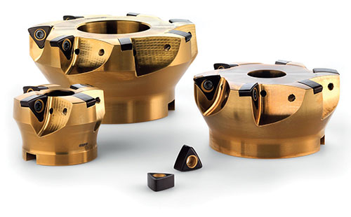
High-feed inserts, such as those mounted on these DAH 62 series tools, are characterized by large, rounded cutting edges and extremely low lead angles.
The lower the lead angle, the thinner the chip and the smaller the force on the tool. To maintain the proper chip load, feed rates must be increased to compensate.
Share


For any shop tasked with heavy hogging, chances are good that the go-to strategy involves taking a light cut at a heavy feed rate. The increasing popularity of this approach has been driven by the advent of roughing insert geometry that takes advantage of chip thinning to maximize both metal-removal rates and tool life.
Among the latest high-feed cutting innovations is the recently expanded DAH milling series from Horn USA (Franklin, Tennessee). Although the new DAH 62 series tools offer their own advantages, they also operate according to the same basic principles that govern virtually all high-feed offerings. During a recent conversation, Jason Farthing, responsible for technical sales and marketing, offered insights into some of the common design features that make high-feed tools so effective, as well as what makes Horn’s tools different.


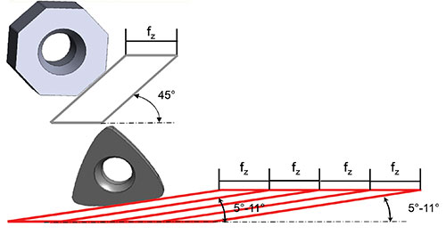
All inserts are designed to remove a certain size chip, a value commonly expressed as feed per tooth, Mr. Farthing explains. Mounted at a 90-degree lead angle, a straight insert at the properly calculated rpm will produce a chip that is theoretically the same thickness as the programmed feed per tooth. Reduce the lead angle, however, and the chip becomes thinner because the cut is spread over a wider
portion of the edge. Arriving at optimal chip thickness requires increasing feed per tooth to compensate.
High-feed inserts like the DAH series trigon cutters, which are mounted at lead angles ranging from 5 to 11 degrees, push this chip-thinning effect to the extreme. In fact, DAH inserts can run at four times the feed rate as a 45-degree-lead-angle tool while maintaining the same chip thickness, Mr. Farthing says. He adds that these and other high-feed inserts also have large, rounded edges that further contribute to chip thinning.
These design features also contribute to the stability required to run at the parameters typically associated with high-feed cutting. The large edge radius, for example, adds strength by distributing cutting forces for more even tool wear. And, along with the low lead angle, it serves to direct machining forces axially up into the spindle rather than radially against the side of the tool. With a lower side load, the tool experiences less vibration and is less likely to pull out of the spindle, Mr. Farthing says. Beyond geometry, high-feed tools like the DAH series tend to use TiAlN-based chemical vapor deposition (CVD) coatings to disperse heat, aid chip evacuation and reduce built-up edge.
One such coating is among the features introduced with Horn’s DAH 62 line, which is designed for more aggressive cutting compared to the established DAH 37 series. While suitable for a range of materials and applications, the SC6A grade improves on the performance of the SA4B grade, particularly in cast materials, steels and nodular irons, he says. In addition, the DAH 62 series’ triple-edged inserts are twice as thick as those on DAH 37 cutters. They also offer a geometry that aids in directing chips away from the cutter body—a feature Mr. Farthing describes as “more of a chip former than a chip breaker.”
Depending on the material, the new grade and design support cutting depths ranging to 2.1 mm at 3-mm-per-tooth feeds, compared to 1.2-mm depths at 3-mm-per-tooth feeds for DAH 37 tools. Also notable is the fact that all DAH 62 tools use the same inserts; the case is the same with the DAH 37 tools. Common inserts for each series make tool management easier from a logistical standpoint, he notes.
The DAH 37 line includes round-shank and screw-on milling cutters in four diameters: 20, 25, 32 and 40 mm. The DAH 62 series expands that range with four interchangeable tool bodies offering cutting diameters of 63, 80, 100 and 125 mm. All holders feature inner cooling and TiN coating to protect against chip wash.


.png;maxWidth=300;quality=90;format=webp)
Related Content

Finding the Right Tools for a Turning Shop
Xcelicut is a startup shop that has grown thanks to the right machines, cutting tools, grants and other resources.
Read More
Choosing the Right Drill Type
Specifying the right option for your application can save time and tools.
Read More
Picking the Right End Mill
Kennametal global product manager Katie Myers explains how cutting tool features can impact machining strategies for different materials.
Read More
Custom PCD Tools Extend Shop’s Tool Life Upward of Ten Times
Adopting PCD tooling has extended FT Precision’s tool life from days to months — and the test drill is still going strong.
Read More