Chatter Control For The Rest Of Us
This shop finds stable milling speeds quickly using a systematic pattern of test cuts.
Share


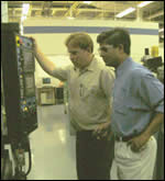
Kevin Berry and Edwin Gasparraj oversee a milling cycle designed to isolate optimal cutting conditions. The two use a quick, systematic pattern of test cuts to determine productive spindle speeds and depths of cut for particular combinations of spindle and tooling.

Here is a test workpiece, photographed after machining the last stepover depth listed in the chart on the facing page. Stable cutting occurred at 7,000 rpm and 9,500 rpm.
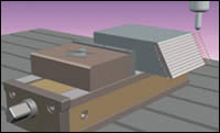
This illustration of the test setup shows the pattern of milling passes for the angled test piece. The radial depth of cut (stepover) is the same for each of these passes, but the spindle speed for each pass is different. When these passes are run again, the radial depth is increased and all of the same spindle speeds are repeated. Testing continues in this way until stable speeds are isolated.

Both of these slots were milled with the same tool in the same machine. Chatter is the difference between them. The smoother pass was run at some optimal milling speed where the chatter quiets down, making it possible to achieve a higher rate of metal removal.
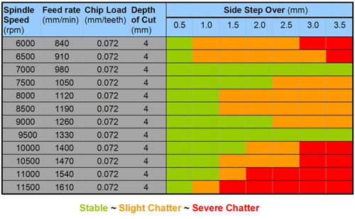
This chart (click to enlarge) summarizes the test results for one combination of tool, toolholder and spindle. Running this test took about half an hour. The green region indicates stable cutting.
When Kevin Berry's shop bought its first high speed machining center, Mr. Berry didn't realize he was getting the metalworking equivalent of a violin. But that's one way to think about high speed milling.
A bow passing across the string of a violin creates a continuous interaction between bow and string that produces a sound. The sound is either sweet or grating, depending on the finesse of the violinist.


In the same way, a milling cutter passing over a workpiece sets up an interaction between the tool and work. The tool and spindle together are vibrating. The vibration leaves tiny waves on the part. The waves might cause the cutting edge to experience a variable load. We call this effect chatter. Like the sound of the violin, the high speed milling pass can be either grating or sweet.
Finessing The Cut
One common way to deal with chatter is to reduce the depth of cut so there is less force to feed the vibration. Another common approach is to increase the system's rigidity, perhaps by switching to a shorter tool, or perhaps by adopting a type of toolholder (such as shrink fit) that has a tighter grip.
With a high speed milling spindle, there is potentially an even better option. "High speed" here means a spindle that is capable of at least 10,000 rpm or 15,000 rpm. When the spindle can go at least that fast, chances are good that some seemingly magic speed along the rpm range will cause the chatter to quiet down, making it possible to take a heavier depth of cut.
The effect may seem like magic, but the explanation is quite rational. At that particular speed, the rate of cutting edge impacts synchronizes with a natural frequency of the system. Although the tool is still vibrating, the cutting load is no longer fluctuating. As a result, it may be possible to cut much deeper before reaching the chatter threshold. Metal removal rate goes up. Efficiency goes up. The trick is simply to find this optimal speed.
Because the spindle and the tooling make up a single system, this optimal spindle speed will be different every time a different style of toolholder or cutting tool is used. Finding and using these optimal speeds can therefore entail the odd challenge of remembering various particular speeds for various combinations. However, the challenge is not insurmountable.
Mr. Berry knew all of this. What he did not know is how—from a practical standpoint—to go about finding these speeds.
What If A Few Tools Do A Lot Of Work?
Mr. Berry works for Lexmark, the maker of laser and inkjet printers. At the company's headquarters in Lexington, Kentucky, a machine shop helps to prototype new printer designs for evaluation and testing. Early stages of a printer's evaluation can use physical models as stand-ins for the printer components, but when the testing of a printer's performance becomes more rigorous, only a molded component can be used wherever the design will call for a molded part. Mr. Berry is part of the mold and tool services department that makes molds for this purpose. The molds that his shop makes have short leadtimes and they are made for short-run use. Many of the molds are also subject to ongoing modifications, as engineers continually refine their designs.
EDM previously made this tooling, and EDM is still used where challenging features of the mold demand it. But the shop has gotten away from relying on EDM so extensively for short-run tooling. The process of making an electrode and burning a part was not responsive enough when a mold was needed particularly quickly, so the shop bought a Makino V33 vertical machining center with 30,000 rpm to help it deliver its mold tooling in less time.
Mastering chatter was the key to maximizing the responsiveness of this machine. Chatter is no fault of the machine tool; it's the fault of physics. Every system of spindle, toolholder and tool has some set of frequencies at which it naturally wants to vibrate. At certain higher spindle speeds, it becomes possible for cutting edges to strike the part frequently enough that the impacts cleanly synchronize with one of these natural frequencies. The smooth cutting that results makes it possible to mill deeper without straining the tool or the machine. In too many machining processes, chatter is the barrier that defines the maximum cutting parameters, when the limits should instead be defined by the strength of the tool and the power of the machine. The narrow zones of stable, optimal spindle speed are the gaps in the wall of chatter that allow this barrier to be surpassed.
Some users of CNC machine tools do recognize this. These shops tend to make aircraft parts. They mill big aluminum workpieces at high spindle speeds, and overcoming chatter makes it possible for them to hog out the metal at a much faster rate. Shops such as these use electronic instruments to measure the frequency response of every combination of spindle, tool and toolholder they are likely to put together. But Mr. Berry's application couldn't justify the expense of purchasing this equipment along with the time that would be required to learn how to use it well.
"I have four favorite roughing tools," he says. "Each one uses the same toolholder every time. I have one high speed machine. If I can learn the right speeds for just these four cases, then that would cover 90 percent of all the roughing that I do."
Relying on an outside source to perform this testing was another option, but Mr. Berry preferred to be able to do the work himself. What if some unusual mold called for a long-overhang tool that wasn't running effectively because of chatter? Mr. Berry wanted to be able to respond to such a problem without waiting for outside help.
The answer came from his CAM software supplier, UGS [now Siemens PLM —ed.]. Edwin Gasparraj, based at UGS's office in Milford, Ohio, had given some thought to this problem. Mr. Gasparraj is product manager for the company's NX Machining products, which include CAM software engineered for the elaborate tool paths of mold machining. This emphasis on intricate tool paths is ironic, because Mr. Gasparraj's patent-pending program for finding optimal speeds involves nothing but milling straight and parallel lines.
The Results
This program from UGS offers a systematic approach for machining at various speeds and depths of cut in order to locate the most efficient conditions. The specific procedures—procedures you can replicate—are outlined in one of the sidebars below.
A set of results is shown in the chart above. In this particular test, the tool cut smoothly at 7,000 rpm and 9,500 rpm, even though it might have been capable of 11,500 rpm in the P20 steel used to test it. Having two different stable speeds available in this way is not overkill, says Mr. Berry. As long as the machine, tool and toolholder are the same, the stable values of rpm transfer from one workpiece material to another. The corresponding depths of cut do not transfer (these have to be determined separately), but the speeds remain the same. Therefore, Mr. Berry would run this tool at 9,500 rpm in P20, but if the same tool was used in some harder-to-machine metal that demanded a lower value of cutting speed (sfm), then having the option of 7,000 rpm available would be valuable.
A limitation of this test-cutting procedure relates to tool size. Mr. Berry uses these test cuts to find the right parameters for tools 6 mm, 8 mm and 10 mm in diameter. For tools much smaller than this, the procedure doesn't work. The sound of the cut becomes too faint to hear the chatter, and the chatter marks in the workpiece become too small to see.
When the tool is large enough, though, the simplicity of this procedure makes it a valuable resource. The right speed and depth for a new tool can be obtained in less than half an hour. When Mr. Berry needs to run a new tool, establishing stable cutting conditions in advance can provide an efficient approach. Even to run just one part, finding the right parameters before machining the job may take less time than it would take to struggle with that tool at some less-than-ideal set of conditions.
MRR Multiplier
The chart illustrates the productivity improvement for one of those tools that the Lexmark shop uses all of the time. In the hope of machining as productively as possible, Mr. Berry might have chosen to run this tool at its top permissible speed of 11,500 rpm (based on the tool supplier's recommendations). If he did that, his chatter-free radial depth of cut would be limited to 0.5 mm. Metal removal rate would be 0.5 × 4 × 1,610, or 3,220 mm3/min.
Compare that to cutting at a stable speed. Slowing down to 9,500 rpm permits a chatter-free radial depth of 3.5 mm. Now the metal removal rate is 3.5 × 4 × 1,330, or 18,620 mm3/min. Productivity increases by almost six times. Even the slower stable speed, 7,000 rpm, permits a metal removal rate that is four times as high.
Ironically, cutting in this way doesn't look much like high speed machining. On a machine with 30,000 rpm available, the natural desire is to use as much of that rpm as the tool can take. But that approach doesn't necessarily make sense. The practice of combining high spindle speeds with light depths of cut might be wasteful if a dramatically deeper cut is possible at some lower speed.
If the machine is like a violin, in other words, then Mr. Berry wants to use it like one. He doesn't want to waste his company's time on using it inefficiently (or otherwise fiddling around).


Related Content

Inside a CNC-Machined Gothic Monastery in Wyoming
An inside look into the Carmelite Monks of Wyoming, who are combining centuries-old Gothic architectural principles with modern CNC machining to build a monastery in the mountains of Wyoming.
Read More
Controlling Extreme Cutting Conditions in Large-Part Machining
Newly patented technologies for controlling chatter and vibration during milling, turning and boring operations promise to drastically reduce production time and increase machining performance.
Read More
The Benefits of In-House Toolmaking
The addition of two larger gantry routers has enabled a maker of rubber belting products to produce more tooling in-house, reducing lead times and costs for itself and its sister facilities.
Read More
Ballbar Testing Benefits Low-Volume Manufacturing
Thanks to ballbar testing with a Renishaw QC20-W, the Autodesk Technology Centers now have more confidence in their machine tools.
Read MoreRead Next

Ten Questions About Chatter
If you want to use a high speed milling spindle to machine aggressively, then information about chatter should be more than just background noise. Here are some basics.
Read More
OEM Tour Video: Lean Manufacturing for Measurement and Metrology
How can a facility that requires manual work for some long-standing parts be made more efficient? Join us as we look inside The L. S. Starrett Company’s headquarters in Athol, Massachusetts, and see how this long-established OEM is updating its processes.
Read More