Ten Questions About Chatter
If you want to use a high speed milling spindle to machine aggressively, then information about chatter should be more than just background noise. Here are some basics.
Share


If you want to use a high speed milling spindle to machine aggressively, then information about chatter should be more than just background noise.
Here are some basics:
What is chatter?
It's not just vibration. In machining, chatter is the vibration that feeds on itself as the tool moves across the part.
Chatter "feeds on itself" — what does that mean?
The tool, toolholder and spindle together will vibrate at some natural frequency—a frequency at which this assembly "naturally" wants to vibrate. In fact, the assembly is likely to vibrate at more than one such natural frequency at the same time.
At the tool tip, this vibration leaves waves in the machined surface. The waviness can cause the next cutting edge to experience a variable load. When that happens, this variable load feeds the vibration that already exists, making it worse.
"Self-excited vibration" is one term for this phenomenon. "Regeneration of waviness" is another.
Why is chatter bad?
The finish of the part is affected; you might be able to see the chatter marks clearly. If chatter persists, the life of the spindle may also be affected.
However, the more immediate and serious consequence relates to efficiency. Most shops deal with chatter by setting their machining parameters low. Therefore, instead of tool strength and spindle horsepower defining the metal removal rate, chatter becomes the limiting factor that keeps the process from reaching its potential.
What can be done?
Increasing rigidity is one option. Use a shorter tool or toolholder, or switch to a toolholder that clamps the tool more rigidly—these are examples of changes that might make the process less apt to vibrate.
When milling at high spindle speeds, there is a potentially more promising option. Certain limited ranges of spindle speed may be stable zones. Within these ranges, the rate of cutting edge impacts synchronizes with a natural frequency of the system. The chip load becomes level, so the cut is smooth. The depth of cut can therefore be increased, and sometimes it can be dramatically increased.
Is there just one stable speed range for every spindle?
A stable value of spindle rpm applies only to a particular combination of spindle, tool, toolholder and tool overhang length. These four factors make up a complete assembly. Every different assembly has to be evaluated separately; evaluating just the spindle is not enough.
However, any particular spindle and tooling assembly is likely to have more than one stable zone. Therefore, finding just one stable speed zone might not be enough. Another, much faster speed may also be stable.
Why does this discussion focus on high speed spindles?
In general, milling at a lower speed—say, in the neighborhood of 4,000 rpm—is not going to offer the opportunity to find an rpm value that permits dramatically greater metal removal. The threshold of chatter will vary by only a small amount throughout this region. This chatter can be addressed by increasing rigidity. It might also be addressed by using a cutter design with variable edge spacing, so that waves in the surface don't appear at such regular intervals.
However, on a spindle that has a maximum speed of 10,000 rpm or more, the potentially more effective solution becomes possible. It is likely that the chatter can be addressed by finding some optimal speed that permits a much greater depth of cut.
How do I find this optimal speed?
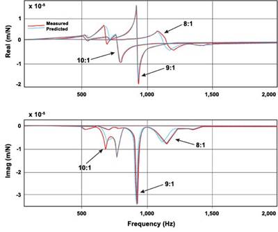
It can be done experimentally, through test cutting. (See "Chatter Control for the Rest of Us" for an example.) It also can be found through measurement, using a tap test. This test involves tapping the tool with a delicate hammer and measuring the frequency response with electronic equipment. The resulting graph of frequency response will suggest the system's various stable speeds. There is even software available that accomplishes something similar by listening to the cut with a microphone. (See "Sweet, Sweet Spot .")
How do I put this information to use?
For every spindle, tool, toolholder and tool overhang combination that you want to use effectively at high speeds, you should find the optimum spindle speed, along with the corresponding depths of cut you have been able to achieve in the various materials your shop runs.
Feed rate is not included here, because feed rate has less effect on chatter.
Make all of this speed and depth-of-cut data available to programmers. They should then refer to this matrix of optimal cutting parameters whenever they use a particular combination of machine, tooling and workpiece material.
If the cut is stable, has vibration stopped?
No. The cut is stable because the cutting edge impacts are timed with the vibration. The tool is still vibrating. Therefore, accuracy needs to be watched; the vibrating tool might not place a machined surface precisely where expected. The phenomenon is called "surface location error" (see "Understanding Surface Location Error ").
What is tool tuning?
Tool tuning (see "The Overhang Effect ") might be thought of as the next step. The shop that has mastered finding and using its optimal speeds might then consider modifying those optimal speeds.
One way to do this is through the tool overhang length. By playing with this length, the stable speed zones might be changed. It might even be possible to use all of a machine's available spindle rpm effectively, by manipulating the tool overhang so that a stable speed zone coincides with the spindle's maximum rpm.
Related Content
To Understand Machine Speeds, Look Past the Spec Sheet
The real-world behavior and performance of a machine depends on use case much more than the numbers listed on its spec sheet.
Read MoreYCM Alliance Five-Axis VMC Enhances Machining Performance
YCM’s RX65+ VMC is engineered for speed, rigidity and accuracy in demanding applications.
Read MoreUnited Machining Solutions' Wire EDM Supports Lights-Out Machining
United Machining Solutions’ Agie Charmilles Cut P 350 Pro features a robust design, the Uniqua human-machine interface and multiple automation options.
Read MoreSW North America Open House Showcases Advanced Machining Solutions
SW North America hosts its 2025 Open House at its Michigan headquarters, featuring live demonstrations of the BA 322i and BA Space3 machining centers with a focus on medical and aerospace applications.
Read MoreRead Next
The Overhang Effect
The length by which the tool extends from the toolholder is a variable that can be used to 'tune' the machining process. Contrary to what you may expect, increasing the tool's L:D ratio may reduce chatter and result in more productive milling.
Read MoreChatter Control For The Rest Of Us
This shop finds stable milling speeds quickly using a systematic pattern of test cuts.
Read MoreSweet, Sweet Spot
For this aerospace job shop, harmonizing key aspects of each high speed machining process creates a "sweet spot" where productivity jumps. Harmonizing other key aspects of shop operations also creates a "sweet spot" that helps the company capitalize on this jump in machining productivity.
Read More


