Cutting With A 0.001-Inch End Mill
JPL’s Space Instrument Shop does this routinely, but it takes some special equipment and some unusual procedures. Above all, it takes patience.

Share


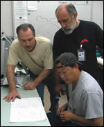
Work at the Space Instrument Shop is highly collaborative. The team consists of Pete Bruneau (left), Hal Janzen (right) and David Evans (seated).
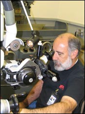
Hal Janzen uses the Ewag cutter grinder to produce the smallest end mills used in the shop. This work is done with the aid of a microscope. Everyone in the shop has “trained their eyes” to recognize and identify objects under magnification.
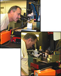
(top)Pete Bruneau uses the microscope integrated to the column of the DAC milling machine for setup. (bottom) A second microscope mounted to the table allows him to observe the machining operation in progress.
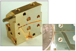
The inner face of this sample sub-millimeter microwave block is about 0.75-inch square. A penny placed next to the wave-guide channel port indicates the scale of the features machined by JPL’s Space Instrument Shop. Photos courtesy of JPL.
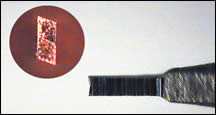
The tip of this end mill is 0.001 inch wide. The inset shows the tip head on, revealing the relief angles on the sides and at the center. Photo courtesy of JPL.
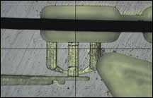
This is how details of the wave-guide channel appear through a high-powered microscope. The smallest channel is 0.0013 inch wide. The smallest end mill used was 0.001 inch wide. The heavy black bar across the top of the image is the profile of a human hair. Photo courtesy of JPL.
The Jet Propulsion Laboratory (JPL) in Pasadena, California, is NASA’s premier research and development facility. It is staffed and managed by the California Institute of Technology (Caltech), a leading private university. Satellites, space telescopes and planetary explorers are designed and built here. JPL is home to some of the most advanced and capable machine shops in the country. One of these, the Space Instrument Shop, is very small. It employs three machinists, houses about a dozen machine tools and is equipped with various pieces of inspection and measurement technology.
The shop’s mission is to produce components for scientific instruments that allow space vehicles to gather, analyze and transmit information about the earth and other parts of our solar system—or beyond. Typically, these are components that other shops outside of JPL are unable or unwilling to produce. That’s because machined features on these parts may have dimensions that are fractions of the width of a human hair and have tolerances as low as ten millionths of an inch (less than a micron in metric terms).


Prime examples are sub-millimeter microwave blocks that are used to mix or boost the frequency of microwave signals ranging from 600 gigahertz to 2.5 terahertz. They are critical components in instruments and for applications such as detecting and measuring the presence of CO2 and other gases in the upper atmosphere. This information helps monitor climate change or predict weather patterns.
Finished blocks are roughly the size of a rectangular sugar cube or a pair of dice. These blocks are produced as a set of perfectly matched halves. When assembled, the internal features of the mating surfaces include microscopically small channels and pockets that must line up within 100 millionths of an inch. The most important features are the wave-guide channels. These are square-bottomed channels that form contoured paths through which the signals pass. The walls of the channel must reflect the signals precisely in order to modify the frequency as intended. The average width of such a channel is 0.002 inch.
For this kind of work, the shop often uses spade-type end mills as small as 0.001 inch wide, although even smaller tools have been used occasionally. Cutting with end mills of this size is representative of this shop’s capability, and it gives a glimpse into the world of machining on a microscopic scale. As parts for medical applications, handheld computer devices and consumer products become smaller and smaller, other job shops and machining labs will have to learn many of the lessons that the Space Instrument Shop has already mastered.
According to Hal Janzen, shop lead, producing parts with features visible only with magnification is vastly unlike the world of ordinary machine shop operations. Procedures for setup, tool-length setting, deburring and other production steps are rather different. The habits, outlook and discipline of the shop team are also distinctly characteristic. Formulas for machining parameters, rules of thumb and expectations that apply in the average shop often do not apply here. Skill, experience and insight are necessary to work in this shop, but perhaps more important are a willingness to experiment, the ability to think creatively and a generous capacity to be patient. “Patience, patience, patience” is Mr. Janzen’s mantra.
The Pace Defines The Place
The Space Instrument Shop has its own self-contained area in Building 168 at JPL’s extensive campus, where more than 5,000 are employed. The shop’s work team consists of two others besides Mr. Janzen, who has 42 years of experience in machining. Pete Bruneau is a senior machinist with more than 25 years of machining experience, and David Evans is the “new kid,” having worked in the shop for only two years following 15 years as a machinist.
The shop is set apart because the machining techniques and equipment are unique among those utilized at JPL’s other machine shops. Its location is also more accessible to the engineers and scientists whose projects involve the Space Instrument Shop. Interestingly, none of the specialized equipment is so unusual that other shops would be mystified by the appearance or configuration of the shop’s vertical machining centers, milling machines and grinders. In many ways, the Space Instrument Shop looks a lot like an everyday job shop.
What is markedly noticeable is the pace of the work conducted in this shop. It’s intense but not rushed. “You have to take your time with everything you do,” Mr. Janzen says. He and his team must go about their procedures methodically, consistently and very attentively. Successful results are never guaranteed, and predicting how cutting tools will perform is often impossible. “This is not a place for the easily frustrated,” Mr. Janzen says.
Yet working here is very rewarding, he contends. One of the roles that this shop fulfills is to advise some of JPL’s top scientists, researchers and engineers. They are constantly working to develop systems that are more powerful, more sensitive or more capable. They come to the Space Instrument Shop to consult on the manufacturability of new designs. This means that the space instrument team gets involved in projects in the earliest stages and often sees them ultimately put into production in their own shop. “We take some of these innovations from the cradle to the grave,” Mr. Janzen says, but it would be more accurate if he had said from “sketch pad” to “launch pad.”
Because JPL scientists are interested in higher and higher frequencies for microwave devices, the designs of the microwave blocks are becoming more intricate and the necessary internal wave-guide channels must be smaller and smaller. The Space Instrument Shop is currently getting ready for the next generation of microwave blocks. As it is, production techniques are already extreme. Here are some of the key steps in machining these workpieces.
The Same Yet Different
Machining the wave-guide channels and pockets in the blocks is a bit paradoxical. As Mr. Janzen points out, all of the elements found in an ordinary machining operation are here. You need the right cutting tool, the right machine tool, the right setup, the right CNC program, and the right way to apply coolant. Yet each of these elements is adapted specifically to machining on a microscopic scale.
The blocks are produced in two major steps. First, matched sets of half-blocks are machined on one of the shop’s two Bostomatic VMCs and precision-ground on an older but well-maintained Thompson surface grinder. The material is usually a high grade of naval brass alloy. Each side of a block must be parallel and perpendicular to within 0.00005 inch and each block must be square to within 0.0001 inch or better. As the box at right shows, preparation of the blocks is extremely important. Mr. Janzen emphasizes that it sets the foundation for successful machining in the next step.
In this second step, the wave-guide channels and pockets are machined on either one of the Bostomatics or a modified three-axis milling machine from DAC International (Carpinteria, California). The smallest channels are machined on the DAC. This machine was originally designed to mill lenses that are surgically implanted in the eye for vision correction (intraocular lens haptics). The machine is based on a granite surface plate that is mounted on vibration isolators on a welded steel frame. The Space Instrument Shop replaced the X, Y and Z slides with high-precision Schneeberger slides and installed larger servomotors to run at slower feed rates without overheating. Heidenhain glass scales provide position feedback in 10-nanometer increments. Mr. Bruneau is the chief operator of this machine and he is responsible for most of the retrofits and enhancements.
Two microscopes are some of the most important features of each milling machine. One microscope is integrated into the column of the machine so that its focal point is at a fixed, known distance from the spindle centerline. This single-eyepiece microscope is used to align the block halves and find their position relative to the tip of the cutting tool. In the machine jog mode, the operator touches the tip of the tool to the workpiece surface to create a witness mark. After jogging the workpiece over to the viewing area under the microscope, the operator can place the crosshairs on this witness mark and offset the point coordinates to check the relationship of the cutter tip centerline and microscope centerline. A similar procedure is used to find the edges of the blocks and align them so that the blocks are symmetrical to the home position of the program. This step ensures that any variations in the workpieces will create mirrored effects in the machined features and still achieve perfect alignment of these features when the blocks are assembled.
The other microscope is mounted on an adjustable swing-away arm that rides on a column mounted vertically to the table of the machine. This binocular-style microscope swings into position to magnify a view of the cutting zone. It is used to set the length of the cutting tool in the spindle, a process similar to workpiece alignment. Each click of the jog button advances the Z axis ten millionths of an inch at a time on the DAC (20 millionths of an inch on the Bostomatics). Each advance can be observed through the microscope. When the rotating tool tip makes contact with the workpiece surface, it leaves a circular mark that is barely visible at 50x magnification. The height in Z at that point is set as zero tool length and the appropriate offsets can be applied to the programmed tool path. This microscope is also used to observe the machining process in action and monitor it for tool breakage or negative cutting conditions such as raising a heavy burr.
The shop produces its own end mills with diameters less than 0.002 inch (larger sizes are acquired from vendors.) Starting with commercially available blanks of super-fine-grain carbide, these end mills are ground on an Ewag WS11 tool grinder (United Grinding, Miamisburg, Ohio). All are two-flute, spade-type end mills with relief angles on the side cutting edges and at the center of the bottom edge to avoid a dead spot. The photograph (below, right) shows a profile of this end mill design. After grinding, the tools are inspected on a Nikon measuring microscope to check for excessive runout (any total above 0.0001 inch is unacceptable).
Tool paths to machine the wave-guide channels are generated with Esprit CAM software from DP Technology (Camarillo, California). The shop uses this software because cutter paths must be postprocessed to six decimal places. Otherwise, inherent programming error would exceed the resolution of the machine’s positioning system. According to Mr. Janzen, cutter path geometry of the channels is usually programmed 0.00015 inch undersized to allow for runout in the end mill.
Although the DAC has an electric air-bearing spindle capable of 120,000 rpm, the shop finds that 90,000 rpm is a practical upper limit. For a 0.001-inch end mill, feed rates are as low as 0.1 ipm. An atomized mist of vegetable oil-based coolant provides lubrication, cooling and chip removal. Proper application of the mist is no trivial matter, Mr. Janzen says.
When machining is completed, the blocks are deburred by hand at a bench under a microscope. Burrs are gently removed with the ground tip of a bamboo chopstick or other type of wood. All edges must be dead sharp. No nicks or edge rollover is allowed. The edges can’t be touched by human hands at this point, Mr. Janzen says, because particles of skin left behind by contact can damage mating surfaces when the blocks are assembled.
After deburring, the blocks are cleaned ultrasonically and inspected on the Nikon measuring microscope. “This is when we discover where the cutting tool may have overshot an inside corner or violated and edge in the test cut,” Mr. Janzen explains. Programmed feed rates can be adjusted to correct for errors. Even when the team is confident about the process, several sets of blocks may have to be machined to yield one that is acceptable for delivery to final assembly.
Seven Effective Habits
Although this simplified description of microwave block machining seems straightforward, Mr. Janzen cautions against that assumption. There aren’t any handbooks or tables to consult when unfamiliar cutting conditions are encountered or when familiar conditions yield unexpected results. Trial-and-error experimentation is sometimes the only option, he says.
Nevertheless, Mr. Janzen emphasizes that good habits need to be cultivated to maximize the shop’s overall success rate. The shop has its own tips for achieving good results and follows them rigorously. Some of the most important items are:
1. Check, check, check. Mr. Janzen and his team purposefully review every step of each procedure to be sure it has been conducted properly. Following mental checklists becomes second nature. Members of the team review activities together to get a fresh perspective. “Everything is important; no detail can be neglected,” Mr. Janzen says.
2. Cleanliness counts. For example, every time a tool assembly or setup is taken apart, each component gets an alcohol wipe before being put back together.
3. Keep machines calibrated. Every machine tool in the shop is laser-calibrated at least once every six months. Even the two Bridgeport knee and column mills used for simple jobs and utility work are “lasered” on a regular basis. The aim of adjustments and realignments is to maintain a like-new or better performance. “You have to have a service provider that understands this goal,” Mr. Janzen says. The shop has been working with Lasers Inc. of nearby Glendora, California, for this service.
4. Spread the work around. To avoid concentrating wear in one part of a machine’s work zone, jobs are set up at different spots on the table. Don’t leave heavy vises or clamping fixtures where the machine has an overhang.
5. Test, inspect, analyze and adjust. That’s how the shop learns from every critical machining operation, and the shop never misses a learning opportunity. Projects are planned and reviewed collaboratively so that the whole team benefits. Logbooks and documentation can capture important information, but experience is the best teacher, Mr. Janzen notes.
6. Keep the lights on. The Space Instrument Shop never goes dark because heat from ceiling lights affects ambient shop temperature. High-intensity task lighting is turned off quickly when not needed because small tools and workpieces can absorb heat rapidly. Holding a constant temperature is the main thing.
Don’t Worry. Be Humble.
7. There is a lot to be humble about. “We are always looking for new tools, new techniques and new thinking,” Mr. Janzen says. He and his team are aware that they are only a small step ahead of what the researchers and scientists will want them to produce. Being constantly on the edge, however, is never boring.


Related Content

SW North America Open House Showcases Advanced Machining Solutions
SW North America hosts its 2025 Open House at its Michigan headquarters, featuring live demonstrations of the BA 322i and BA Space3 machining centers with a focus on medical and aerospace applications.
Read More
Shop Tour Video: Inside an Aviation & Defense Machine Shop
Grants. Software. Process consolidation. These three pillars can bring new life to a shop, enabling it to take on more complex jobs with faster turnarounds. In this shop tour, find out how MSP Manufacturing has used each pillar to solidify itself as a reliable partner for defense and aerospace companies.
Read More
Taiwan Machine Tool Industry Showcases AI Innovations at EMO 2025
The Taiwan External Trade Development Council highlighted AI-powered solutions for precision and sustainability in manufacturing.
Read More
Kennametal Enhances High-Performance Drill Lineup
The KenDrill HPR Solid Carbide Long Length Drills lineup is well suited for aerospace, transportation, general engineering, energy and earthworks shops seeking increased wear resistance, toughness and durability.
Read MoreRead Next

Fine Wire Is Just Fine
As parts get smaller and smaller, using EDM wire as small as 0.001 inch in diameter to cut these workpieces becomes an attractive option—actually, the only option.
Read More
OEM Tour Video: Lean Manufacturing for Measurement and Metrology
How can a facility that requires manual work for some long-standing parts be made more efficient? Join us as we look inside The L. S. Starrett Company’s headquarters in Athol, Massachusetts, and see how this long-established OEM is updating its processes.
Read More