Getting In Gear With An Automated Cell
This production cell embodies several unusual but very effective concepts for keeping process variables under control with little operator intervention.

Share


Screws for compressors have helical shapes not unlike some of the most demanding gear making applications.
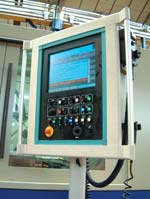
Fig. 6—Machine controls units with touch screen panels allow shop floor data viewing and programming. Cell control software is Windows-based.
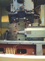
Fig. 5—The autoloader serving the grinding machine saves floor space and keeps the machine in continuous operation.
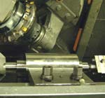
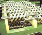
Fig. 1—Helical grooves are milled to full depth with one pass.
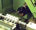
Fig. 3—On-machine probing and compensation are a key to accuracy and throughput.
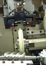
Fig. 4—Diamond dressing wheels maintain the profile of the grinding wheel, which is dressed between each workpiece.
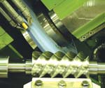
Fig. 2—The inside and outside of the helix are ground with two surfaces of the wheel at the same time.
The world of gear making is used to high standards, but there are other industries that could rightly claim to meet far higher tolerances and accuracies. This accepted wisdom, along with some other fundamental practices in the production of gears, has been challenged by at least one machine manufacturer, Holroyd, a division of Renold Precision Technologies.
The change in thinking and the revised expectations in production speed and accuracy are well illustrated by a compressor screw production line at the company's manufacturing plant in Rochdale in the north of England. How does a compressor screw manufacturing line relate to gear making? The answer is in the use of essentially two machines, the company's 2E high speed screw milling machine and its TG150 thread grinding machine with precision on-board measurement and self-correction features.


Although in this application they are being used to produce screws for compressors, both machines are designed to produce complex components with helical screw profiles and are equally at home producing gear parts such as worm shafts. Both machines were designed for this dual purpose and are used and sold as such; however, in the current cell they happen to be producing compressor screws.
The Cell
The so-called "Gemini" production cell at Holroyd produces an average of 40,000 compressor screws a year. In the past year of operation, there have been very few scrap components, and production targets have been consistently met. The reason for this consistency is essentially the use of dry milling, on-machine measurement, and on-machine auto adjustment. Here is a brief overview of the production strategy.
Stress-relieved C1141-grade steel is delivered in bar form, the screw shafts are turned conventionally at both ends, and the blanks are loaded onto the 2E helical deep-groove milling machine. Five helical grooves are then milled from the blanks, leaving 0.010 inch of metal for final grinding.
Spindle shafts and screw ends are then finished on a Danobat CNC lathe. The screws are moved between machines on color-coded pallets to avoid confusion, although they do look significantly different at each stage of the process. The semi-finished screws are then placed onto an automated loader for final grinding on a Holroyd TG150 thread-grinding machine. Every component leaves this machine finished, measured, checked and approved without any need for external measurement equipment.
It is worth mentioning at this point that Holroyd designs and builds all its machines on site. These machines are not only sold to other gear manufacturers but also are used in house to produce finished products for customers who prefer to subcontract the manufacturing. This way of working ensures that the company stays closely linked to achieving the finished product and prevents the company from having to rely on machines out in the field for long term feedback and development work.
Dry Milling Helical Profiles From Blanks
Looking at the important areas of this process in order starts with the 2E thread milling machine. It cuts a 1.0-inch deep and 1.25-inch wide helix groove in the screw blank. The piece is fed in a reverse action back across the cutting head, while rotating past the cutting tool in order to achieve the helix groove profile.
This machine forms a full-depth groove in a single pass and takes only seconds to do it. (See Figure 1.) The cutting head is able to remove so much material in one step because the heat generated is transferred to the chips. The chips are then removed from inside the machine bed on a conveyor. Because little or no heat transfers to the workpiece, no coolant is required. Dry machining is an advantage in the cell configuration because it does not require additional liquid filtering, pumping and cooling apparatus.
Paul Hannah, VP engineering products at Holroyd, comments that, "the chips take the heat here, allowing us to remove a large amount of metal very quickly and without causing a significant temperature change; the piece temperature remains stable at about 6° F above room temperature during cutting. By quickly cutting the blanks to within 10 thousandths of the finished piece we ensure that the finish grinding does not have to remove too much metal, and we achieve the end results in a much shorter cycle time."
Thread Grinding Procedure
After the screw ends and shafts have been finished, the screws are then moved to the thread grinding machine. Screws are transferred to an autoloader feeding the thread grinding machine, but more about that later. The grinder loads each workpiece automatically and clamps it hydraulically using a close-tolerance shaft chuck, being supported at the non-drive end by a hydraulically operated tailstock. The machine checks the part's position against a datum using a precision ruby tipped scanning probe mounted within the machine. The grinding head then generates a first thread/flute to 0.001 inch of the finished size.
The grinding wheel creates the convex or concave curved profile of a male or female screw by grinding out from the center crease with two surfaces of the wheel simultaneously, one side shaping the inside and the other the outside of the helix. (See Figure 2.) The probe then scans the profile to confirm the tolerances. If the profile is correct and within tolerance, the next flute is ground to finished accuracy. That second flute is then checked while still in the machine. If it passes, then the remaining three flutes are ground and the first one is finished, removing the 0.001 inch left by the first grinding pass.
If the part does not meet tolerance requirements after the first flute has been ground, then the TG150 calculates the necessary adjustments to grinding wheel form or axis positions and then redresses the grinding wheel using two diamond-cutting wheels housed inside the grinding wheel arm. After the grinding wheel has been dressed again, another flute is ground to within 0.001 inch and checked. Providing that the tolerances are now met, the next flute is ground to finished dimensions and checked. This step confirms that the adjustment was correct, and the rest of the threads are ground including the first two, which are finished.
According to Mr. Hannah, "the re-dressing procedure is carried out automatically by the machine before the first thread is ground, and rarely does the machine need to make any further corrections after the first pass. On the occasion that it does, the correction is effective, and the second thread passes, the grinding cycle then proceeds as normal. The process is so reliable that if a part did not pass after the machine had corrected more than twice, then we would know there was a problem with either the preparation work or the materials being used, that is, the grinding wheels or the steel."
The main benefits of making measurements and adjustments on the machine during the normal production cycle are that every item is fully checked to the same accuracy as it would be on a CMM. Plus, by removing the need for off-machine measurement, setup times are drastically reduced. This approach improves the speed and repeatability of the overall process.
On-Machine Measurement
According to Mr. Hannah, the TG150 machines are "designed and manufactured to the same specifications and tolerances as a stand-alone CMM." The grinders use the same scanning probes that are used on high-end CMMs. The grinders also use closed-loop servo motion control systems with high-precision encoders and scales that are similar to those found on a CMM. (See Figure 3.) The machines are then calibrated to the same standards as a CMM to guarantee the accuracy required. "We no longer have to physically remove a product to check and validate machining tolerances," Mr. Hannah says.
This machine sidesteps the thorny question of environmental conditions, crucial to the reliability of external measurement techniques. The probe is mounted internally; it exists in the same environment as the machine, and so temperature fluctuations among machine tool, work item and measurement device do not occur. If environmental conditions change, the machine adapts.
A simple probe calibration routine at the start of each scan cycle provides a validated reference point to begin machining. Mr. Hannah points out that the probing cycle itself takes place without any machining forces and is therefore dynamically and kinematically stable—the weight, precision and stability of the machine bed being comparable to a CMM when the machining elements are static. The workpiece is held in the same fixture as used for machining, so there is no loss of position for corrective rework.
Errors that inevitably arise during re-moval and transport of the part to a remotely sited CMM are eliminated. The piece does not have to be reloaded into the machine and then re-ground and removed again for validation of the correction. There is also an obvious (and major) cost advantage to be gained here; by avoiding breaks in production to check accuracy, throughput is maximized, and the thread-grinding machine works at its most efficient and productive level.
On-Machine Dressing Of Grinding Wheels
To complete the work—test—rework cycle on one machine, two on-board diamond disks dress the grinding wheel. Figure 4 shows these components in black on a machine during build-up. Mr. Hannah describes this feature as the main element in removing "the black art" of precision machine setup. "Operator skill level is always a variable in complex machining processes, and accurate adjustment often takes years of knowledge and experience to perfect," he says.
Holroyd claims to have distilled this knowledge and experience into the operating intelligence of the machine. Using the data from on-board measurement, it is able to accurately predict the minute alterations to the profile of the grinding wheel needed to achieve the desired result and make the changes on the fly. Routine wear in the grinding wheel is also addressed this way because the dressing process is carried out before every new piece is ground.
Grinding wheel replacement is highly predictable. The level of on-board adaptation offered by the machine also means that setup times for new component runs are reduced because most of the setup is automated.
Autoloader
Given the number of workpieces this cell produces, its compactness is remarkable. One main reason is the auto-loader feeding the TG150 grinder (see Figure 5). In order to maximize the machine's operating time, semi-finished parts ready for final grinding are loaded onto a conveyor. The machine then uses a servo driven crane and gantry system to pick each component and load it as soon as the machine is ready.
This is the only aspect of the cell that has been updated since it was first installed. This update allows three additional com-ponents to be completed per shift.
The Results
Interlocking screws such as the ones produced by the Gemini cell are used in air/gas compressors, refrigeration systems, vacuum pumps and general precision fluid pumping applications. The accuracy demanded by these applications can be within 0.00025 inch over the complete curved surface, which represents one of the most precise industrial tolerances. Some gear production undoubtedly does not require these levels of accuracy, but it defines the current limit that gear production can achieve. The profiles may change when producing gear parts, but the accuracy remains.
Overall, Holroyd claims to have reduced by half the time taken to produce a batch of finished components using the Gemini cell when compared to more traditional methods of machining, measurement and adjustment. The company also claims that the cell achieves a level of repeatable accuracy that is an order of magnitude higher than other systems requiring a similar investment. This has made applications calling for screw


Related Content

Addressing Manufacturing Challenges with Automation
GrayMatter Robotics’ Physical AI robotic cells for manufacturing offer immediate impact and results.
Read More
The Keys to Combining High- and Low-Volume Production
Process expertise and precise production planning enable the Kinetic Company to produce both high- and low-volume jobs requiring machining, grinding, heat treatment and other processes.
Read More
ANCA Celebrates 50th Anniversary
ANCA CNC Machines is celebrating its 50th anniversary as a global producer of CNC tool and cutter grinders.
Read More
Three Key Factors For Stabilizing a Grinding Operation
Improving throughput in grinding takes more than direct increases to material removal rate. It also requires careful consideration of the factors behind the operation’s stability.
Read MoreRead Next

OEM Tour Video: Lean Manufacturing for Measurement and Metrology
How can a facility that requires manual work for some long-standing parts be made more efficient? Join us as we look inside The L. S. Starrett Company’s headquarters in Athol, Massachusetts, and see how this long-established OEM is updating its processes.
Read More