
In-House Measurement For Bi-Rotary Heads
Generally the method required to verify a four-or five-axis, bi-rotary head machining center involves sophisticated laser interferometers and time consuming machine mapping to define and correct axis deviation from wear or other causes. For most shops, this calibration is done by an outside service.

Share


A new device for bi-rotary head machining centers enables shops to perform calibration and measurement at will, in-house.
Graphics on the CNC screen step the operator through various measurement and calibration routines. The skill level of the interactive system is designed to match the skill level of a five-axis machining center operator.
A five-side machining program can be thought of as five different three-axis programs stitched together. Does that mean the task of programming a five-side job has to be five times as difficult, or five times as time-consuming?
Accuracy is a continuous process for metalworking shops. Customers demand consistently tighter tolerances over a given run of parts. Often an answer to this need is found in the machine tool being used to cut the workpieces. But machine tools, like cutting tools, are prone to wear.


On most conventional three-axis machining centers, wear can be compensated relatively easily by the use of various devices that accurately track the machine’s linear motion followed by electronic comps entered into the CNC. However, for machines that use more than three-axes and specifically for those that use bi-rotary heads, calibration becomes a more involved process.
The design of bi-rotary head machining centers exacerbates any machine inaccuracy because the cutting tool tip is relatively far from the moving elements of the machine. Any tolerance deviations are multiplied by the distance and by the accumulation of errors that result from the combined multi-axis configuration.
Generally the method required to verify a four-or five-axis, bi-rotary head machining center involves sophisticated laser interferometers and time consuming machine mapping to define and correct axis deviation from wear or other causes. For most shops, this calibration is done by an outside service.
At the recent EMO show in Milan, Fidia Company (Troy, Michigan) showed a new measuring and calibration device for bi-rotary head machining centers. It was developed for the company’s line of high speed machining centers and interfaces with the Fidia CNC, which is commercially available to other machine tool builders.
The aim of developing this head-measuring system is to create a simple and automatic process for calibrating bi-rotary head machining centers that can be used at will in the shop. The calibration cycle time, which can be set to various degrees of need, takes a maximum of 30 minutes for a complete calibration test or a matter of minutes for specific axis measurement checks. The calibration routines are within the skill set requirements of a five-axis machining center operator.
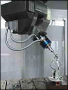
In operation, a base unit is attached by magnet to the machine tool table. Three position transducers are assembled on the base and comprise the measuring system. A sphere on an arbor is inserted in the machine spindle and is positioned manually to contact the three sensors.
The unit is then calibrated (cycle time is 10 minutes) by an automatic routine in the CNC. The relative position of the sphere and the sensors is recognized by this routine and once it is complete, the machine is ready for calibration measurement and testing.
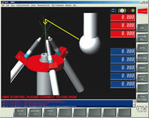
Canned cycles contained in the CNC software algorithms cover the required motion exercises to determine any axis tolerance deviations. Necessary compensations are then made in the CNC. Real-time graphics on the CNC show the operator what’s happening in the test cycle and for traceability and other documentation requirements, reports of the tests and corrective actions can be generated. The precision range of the head-measuring system is comparable to laser interferometers.


