
Keeping 3 + 2 Machining in the Clear with PowerMill’s Dynamic Machine Control Toolbar
Dynamic Machine Control helps the programmer find the most advantageous workplane orientation, cutting tool tilt angle and tool length in order to speed the process of optimizing a 3 + 2 program.


Dynamic Machine Control, a new toolbar added to the latest release of Delcam’s PowerMill CAM software, enables the programmer to check and adjust for potential collisions. This makes machining in the 3 + 2 mode on a five-axis VMC more secure.
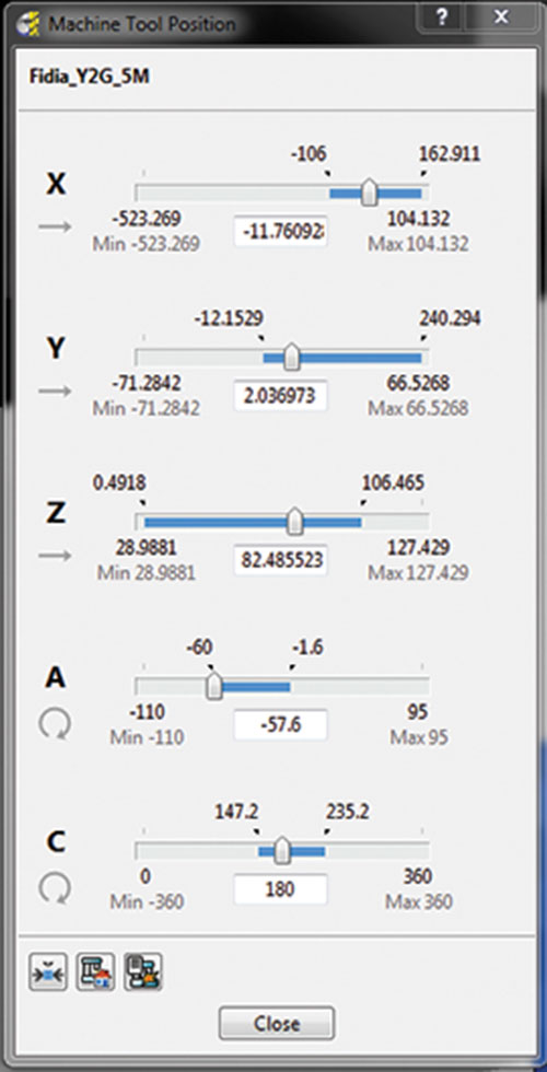
The redesigned Machine Tool Position dialog box, which opens from the new toolbar, provides data on the position of the machine tool, together with limits set for each axis.
Share


CAM software that supports 3 + 2 machining has helped make this technique a valuable option for users of five-axis machining centers. The 2014 R2 release of PowerMill CAM software from Delcam includes new utilities that enable the programmer to more quickly find the most advantageous workplane orientation, cutting tool tilt angle and tool length. This speeds the process of optimizing the 3 + 2 program, and makes checking for collisions faster and more thorough. One of these utilities, Dynamic Machine Control, enables the programmer to simulate the motion of the tool tip dynamically and instantly evaluate the effects of program edits to avoid collisions in the tool path.
Operating in 3 + 2 mode involves using the two rotational axes to lock the cutting tool in a tilted position before executing a three-axis milling program. This combination of three-axis milling and two-axis tool positioning gives this technique its 3 + 2 nickname. The main advantage of 3 + 2 machining is that it allows for the use of a shorter, more rigid cutting tool than would be permissible with conventional three-axis machining.


With 3 + 2, the spindle head can be lowered closer to the workpiece with the tool angledtoward the surface. Using a shorter tool, in turn, enables faster feeds and speeds with less tool deflection. This means that a good surface finish and more accurate dimensional results can be achieved in a shorter cycle time. Other benefits include shorter tool movements, fewer lines of program code and fewer machine setups.
Nevertheless, a 3 + 2 tool path requires the same careful preparation, verification and optimization as a full five-axis part program.
For example, one of the new utilities is a software toolbar that can be opened when a toolpath simulation stops after it detects a potential collision. Called Dynamic Machine Control, this toolbar enables the user to quickly and easily adjust any axis position in an existing tool path in order to avoid the collision. The programmer can test and evaluate these adjustments instantly by dynamically moving the repositioned tool tip around that tool path while it remains in constant contact with each toolpath segment. If this movement of the tool tip detects further collision points, the programmer can click on graphical “grab handles” that enable the tool to be tilted and rotated manually into a new position that avoids the problem area. For each repositioning, the software can create a workplane that is aligned to the adjusted cutting tool axis and machine tool orientation.
To aid this process, the toolbar includes a machine tool position dialog box, also new,that can be opened to view data on the position of the machine tool, together with the limits set for each axis. This dialog box also shows the range of motion set for each axis of the tool in its current orientation. This is depicted by a slide bar representing the travel limits for that axis. Sliding the indicator on the bar automatically controls the position of the tool as displayed in the simulation, and it is a handy way to jog the machine components into position during the editing process. A warning pops up if an axis limit is exceeded.
At any point, the programmer can return to dynamic control of the tool tip. When finished making whatever adjustments in the tilt and rotation of the cutting tool are necessary to avoid all potential collisions, the programmer simply updates the tool path and runs the simulation as an additional check. A video demonstration of Dynamic Machine Control can be found at short.mmsonline.com/clear3+2.
Other enhancements in PowerMill 2014 R2 include an enhanced boundary editing history form, a composite curve creator that merges adjacent arcs and surface edges, an improved hole creation and editing utility, and more.


Related Content

How a Family-Owned Tooling Company Competes with Global Giants (Includes Video)
Not ready to go digital? Consider this: With Siemens NX ecosystem, precision shop D’Andrea cut its programming time by 50% and is able to compete globally—even against industry giants.
Read More
SolidCAM iMachining and Technology Wizard: Faster Machining and Longer Tool Life
Smarter toolpaths to tackle modern machining challenges.
Read More
Can ChatGPT Create Usable G-Code Programs?
Since its debut in late 2022, ChatGPT has been used in many situations, from writing stories to writing code, including G-code. But is it useful to shops? We asked a CAM expert for his thoughts.
Read More
The Power of Practical Demonstrations and Projects
Practical work has served Bridgerland Technical College both in preparing its current students for manufacturing jobs and in appealing to new generations of potential machinists.
Read MoreRead Next

OEM Tour Video: Lean Manufacturing for Measurement and Metrology
How can a facility that requires manual work for some long-standing parts be made more efficient? Join us as we look inside The L. S. Starrett Company’s headquarters in Athol, Massachusetts, and see how this long-established OEM is updating its processes.
Read More