Lean Manufacturing Shapes A Cell
A machining cell that seeks to optimize product flow may look very different from a cell that seeks to optimize a machining process.

Share


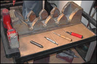
Fig. 1—Although it’s not much to look at, this cart represents a beautifully efficient way to bring deburring and other part prepping steps into continuous flow with machining processes in a cell.
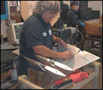
Fig. 4—Brenda Franklin deburrs one fin at a time, flipping it over in a wooden rack to easily reach both sides. By flipping back and forth through the set of fins, she processes all of them with a minimum of handling.
Fig. 2—The design of Precise’s machining cell emphasizes fast throughput rather than fast machining.
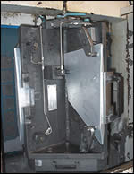
Fig. 3—Pallets with customized fixtures can be exchanged automatically to virtually eliminate machine idle time for loading and unloading.
Beautiful or ugly? It’s how you look at it, of course. Some would say that the objects on the cart shown in Figure 1 are hardly things of beauty. The cardboard mat holding the four deburring tools is smudgy and plain. The wooden rack nearby is nicked and worn. The red battery-powered tool hanging on the cart’s handle has its share of grime.
To Brenda Franklin, however, the cart and it contents are beautiful things. Ms. Franklin is one of the production specialists who works in the machining cell where the cart plays an essential role in the production of “tail fins” for an aerospace application. To her, the cart represents a much smoother, easier and more effective way to clean, deburr and handle each machined fin before it moves to an inspection station. Thanks to this cart and other carefully designed workstations in the machining cell, Ms. Franklin can finish a number of manual operations on four fins while four more are being machined on a CNC horizontal machining center (HMC). The cell provides a continuous flow that takes each fin through virtually the entire production process. That’s the beauty of a cell in a lean manufacturing environment.


The Science Of Cell Design
The cell is located at Precise Machining & Manufacturing, an aerospace job shop located in Tulsa, Oklahoma. Precise produces parts for a number of Boeing units and other aerospace companies constructing commercial and noncommercial aircraft. The flight control surfaces, or tail fins as they are called in the shop, are some of the simpler parts machined here. Many other complex aluminum and titanium workpieces are processed on five-axis machining centers, for example.
The company first began to produce the tail fins in 1994. At that time, the quantity being produced was rather low—456 a month. One machine and one operator were dedicated to this contract. In 1999, however, order quantities jumped up dramatically, reaching 1,600 a month, in a very short period. At the time, Precise had been active in Boeing’s initiative to help its suppliers implement lean manufacturing techniques.
Revamping the tail fin production process was an ideal opportunity to apply the manufacturing techniques that Precise personnel were adopting as part of a concerted effort to be transformed by “lean” thinking. In 2001, the company conducted a series of accelerated improvement workshops (AIWs) focusing on the tail fin production process. TechSolve, a Cincinnati-based lean manufacturing and machining consulting firm, along with representatives from Boeing, acted as facilitators during this period. The most conspicuous result is the three-machine cell that was installed in 2002.
“One of the first things we learned is that the emphasis had to be on the entire production process, the value stream,” says Joe McWethy, one of the company’s manufacturing managers. “The essence of lean manufacturing is creating a production system that produces exactly what the customer needs, exactly when it is needed, in the exact quantity needed.”
He explains that lean manufacturing provides a methodology for creating that system. According to Mr. McWethy, lean thinking made designing the cell almost a scientific process. There was a clear rationale for every element in the cell and a measurable way to prove if every element was fulfilling its purpose.
One of the most important lean manufacturing tools applied in this case was value stream mapping. Value stream mapping is a graphical technique for finding the path to less-wasteful part production. The first step is capturing the “current state” to draw a clear picture of where value is being added—and where it isn’t—in existing procedures. In this case, the current state map helped the company identify the specific issues that had to be addressed:
- Future demand for the fins would quadruple in just a matter of months.
- Manual loading, handling and deburring procedures presented serious safety considerations.
- Quality measures indicated variation in the process below desired capability levels.
- Processes were functioning in pockets without considering the needs of downstream operations.
- Future demand would include a much higher fluctuation in mix between small and large fins.
Value stream mapping then envisions a “future state” that shows how production resources could be rearranged to reduce waste. When creating the future state map, planners envisioned a cell in which all of the non-machining processes would be conducted inside the cell. The objective was to produce the fins based on a precalculated takt time. Takt time indicates how often a part must be produced to meet customer requirements. Takt time helped the shop determine how many machines the cell should have, which cycle times had to be reached and how much time would be available during machine cycling for all other process steps to be completed.
These numbers indicated how much automation, if any, was appropriate. For example, hydraulic clamping fixtures on exchangeable pallets make sense, but installing robotics at this point did not. Likewise, all of the non-machining processes were scrutinized for ways to minimize activities or motions that did not add value. Then these processes were arranged so that fins could move from one to another in a continuous flow—that is, without batching them between the steps.
The Anatomy Of The Cell
The cell consists of three horizontal machining centers. The cell produces two sizes of tail fins—a larger one weighing about 7.5 pounds and a smaller one that is about one third this weight and half the size. Large fins are machined on a Kiwa KNH400 HMC, while small fins are machined on a Toyoda FA450 HMC. Both machines have rotary pallet changers. Each pallet holds a custom fixture, dedicated to either large or small fins, that allows four fins to be machined together in one cycle. A third machine, another Kiwa KNH400, is set up to do either large or small fins. A pallet shuttle allows any two of four pallets (two for small fins and two for large fins) to be mounted in the machine. Figure 2 shows a layout of the cell.
Two workstations are located between the Kiwa and Toyoda machining centers. One workstation holds checking fixtures used to inspect several key features on each fin while the other is a station for inserting two bushings. A personal computer (PC) on the checking fixture bench allows inspection data to be entered on the spot. The checking fixtures and PC are on swivel mounts so they can be used by machine operators on either side of the bench.
The ugly/beautiful cart described at the beginning of this article serves as a part transporter that moves fins from station to station and serves as movable deburring center. Each of the three machines has its own cart.
Fins enter the cell as aluminum castings. Fins leaving the cell for shipment to the customer have been machined, deburred, cleaned, inspected, anodized and fitted with a bushing. An outside subcontractor does anodizing away from the cell, but fins leaving the cell are replaced by anodized fins in matching quantities on a daily basis, so the anodizing step is neutral to both part flow and processing time within the cell.
It’s Not About Faster Machining
It is significant to note that the machining cycle time on the cell is not much different than the cycle time on the machine originally used to produce the fins. All of the productivity increases and quality improvements were gained by adding new machines and performing all other production steps in parallel to machining. In other words, these steps can be completed in the cycle time of the machines (less than half an hour).
One implication of this goal was to zero out time for loading and unloading the machines. This was accomplished by using automatic pallet changers so that the machines are idle only long enough to change pallets, a step that occurs in seconds.
However, loading and unloading the pallets also had to be streamlined. The main contributor here is a set of customized fixtures on each pallet. These fixtures consist of four vertical mounting plates at right angles to each other, as shown in Figure 3. The fixtures were designed and built in house. Cutouts in each plate allow access to both sides of the fin so that the pockets on each side can be milled in one setup. Clamping is hydraulic, providing quick, consistent and repeatable workholding. The design and installation of the hydraulic systems for the fixtures required the expertise of VekTek Inc. (Elwood, Kansas), a company specializing in workholding automation. The previous method of manual clamping required numerous turns with an Allen wrench, a chore that was fatiguing and inconsistent. Improved clamping has also resulted in more consistent machining results.
The time required for other processing activities had to be compressed as well. The carts are a good example. They are used to transport the fins to and from the pallet loading station at the machine to which they are assigned. A simple wooden rack holds the four fins in V-shaped slots.
The fin in the first slot is always replaced by the machined fin removed from station one in the fixture. The fin in the second slot is always replaced with the fin removed from station two, and so on. By maintaining these positions every time a fin is moved from step to step, the fins can be kept in sequential order without marking them. Previously, it was necessary to mark each fin as it came off the machine, but removing the marks before anodizing caused delays and quality issues.
The cart becomes a portable deburring station when the fins are removed from the HMC. The V-shaped slots allow the fins to be flipped over so that the operator can deburr both sides of the fin before moving to the next fin, as shown in Figure 4. Once picked up, a deburring tool is not placed back in its designated cutout on the top tray of the cart until all four fins are finished with that particular step. Finally, the fins are wiped down with a degreasing agent. Speaking from her own experience, Ms. Franklin notes that flipping the fins one way with each step and back the other way for the next step accumulates a significant time savings and requires fewer repetitive motions.
Similar economies of time and effort are derived from the arrangement of the inspection stations. At the inspection bench, each fin proceeds through several gaging and checking procedures and is then returned to its original slot on the rack before the next fin is handled.
After inspection, the operator rolls the cart to a box for shipment to the anodizer and replaces them with anodized fins returned earlier by the anodizer. Delivery of outgoing and incoming fins (a 3-day turnaround) is coordinated so that the flow of parts is seamless.
The cart then moves to the bushing insertion station, where activities have also been streamlined. For example, a hydraulic press replaced the former hand-operated one for inserting the bushing into the underside of the fin. After inspecting the installed bushing and rubber-stamping a unique part number, the operator takes the finished fins to a shipping container for the customer. The empty card is loaded with fresh castings and taken to the HMC, where a waiting but loaded pallet is being exchanged with one ready for unloading.
The cycle repeats. At peak production, the cell operated around the clock in two 12-hour shifts, 5 days a week. Analysis of value-added time and non value-added time as revealed on the current and future state maps prepared during planning for cell shows that value-added time for a part flowing through the cell totals 453 minutes versus 458 minutes before the cell was installed. However, non-valued time dropped from 52.5 days before the move to cellular manufacturing to only 4 days after the move.
Leveling The Production Mix
The role of the third machine in the cell is worth noting. Because it can process either large or small fins, it provides a backup to the other two machines in the cell, allowing them to be idled for scheduled (or unscheduled) maintenance with no disruption to part flow. More importantly, this machine helps level the production mix.
Because order quantities for the two sizes of fins varies (orders for larger fins are usually higher), this third machine can produce the required mix over and above the quantities produced on the other two machines. The pallet shuttle minimizes change-over from one size to the other.
Future State
Because lean manufacturing is an ongoing effort to take waste out of a production process and because Precise takes lean manufacturing very seriously, the company is already looking ahead to further improvements in the fin cell. The most urgent issue on the horizon is establishing better material management tools for flow between the casting supplier and Precise and between Precise the customer.
“We don’t have a true pull system yet,” says Mr. McWethy. As evidence, he notes that the shop stores a large inventory of castings to accommodate the caster’s production schedule rather than the much smaller quantity needed to support the cell’s requirements.
Likewise, the shop and the customer are studying a way to provide visual signaling of delivery requirements. One proposal calls for mounting a camera in the customer’s facility. This camera would be linked to the Internet so that Precise could access its video display to see how many shipping containers need replenishment. This access would eliminate the need for e-mailing this information several times a week.
Finally, Mr. McWethy says that the shop is anticipating an eventual drop-off in orders for the fins. This means developing a future state map for a downsized cell that will continue to meet cost and productivity goals. “We think this will help us repurpose the equipment in a more timely and orderly fashion,” he says. The prospect of downsizing the cell underscores the benefit of designing the cell along lean principles. “We don’t have a lot of specialized automation that might be orphaned when that time comes.”


Related Content

DN Solutions Acquires Heller to Boost Global Machine Tool Market Presence
DN Solutions integrates Heller Group, leveraging a 130-year legacy to enhance machining center technology and expand customer reach.
Read More
Taiwan Machine Tool Industry Showcases AI Innovations at EMO 2025
The Taiwan External Trade Development Council highlighted AI-powered solutions for precision and sustainability in manufacturing.
Read More
SW North America Open House Showcases Advanced Machining Solutions
SW North America hosts its 2025 Open House at its Michigan headquarters, featuring live demonstrations of the BA 322i and BA Space3 machining centers with a focus on medical and aerospace applications.
Read More
Achieving Large Cycle Time Savings on Large-Format Parts
Aero-Tech Engineering sought a faster gantry mill to handle a growing queue of structural aerospace parts. But this machine proved even more productive than expected — and better able to handle the additional jobs its presence won for the shop.
Read MoreRead Next

OEM Tour Video: Lean Manufacturing for Measurement and Metrology
How can a facility that requires manual work for some long-standing parts be made more efficient? Join us as we look inside The L. S. Starrett Company’s headquarters in Athol, Massachusetts, and see how this long-established OEM is updating its processes.
Read More