Manufacturing Speed for Drag Boats
Advanced Design Technologies LLC's subcontracted work led to quality issues among other problems. Vero Software's Surfcam 2017 R1 increased overall efficiency and quality.


Con la ayuda de los engranajes W-Drive y otras piezas personalizadas de Advanced Design Technologies, el equipo de carreras Nitrochondriac estableció un nuevo récord de tiempo para los botes de carreras Top Fuel. El equipo cubrió el recorrido de 304.8 metros en 3.38 segundos a más de 423 km/h en el evento Lucas Oil Drag Boat en Marble Falls, Texas, en agosto de 2016.
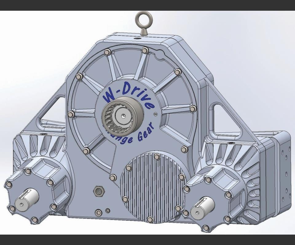
La versión 2017 del W-Drive se aprecia más arriba. Esta transmisión marítima con división de potencia incluye un eje de entrada de un solo motor con dos ejes de salida de hélice contrarrotantes. Los seis engranajes para la sobremarcha de entrada y de salida, además de la distribución de la energía para los dos árboles de salida de la hélice fueron subcontratados inicialmente, pero después de que un engranaje defectuoso se desintegró en un barco que viajaba cerca de 320 km/h, Faulkerson decidió hacer todos los componentes en su taller.
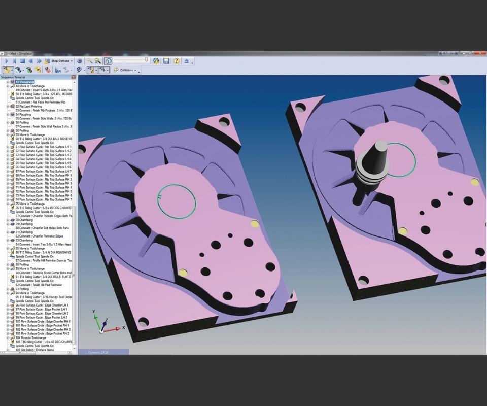
Ambas piezas se pueden desbastar en un solo ciclo usando la función de desbaste integral. En pocas palabras, el ciclo de fresado de desbaste del Surfcam puede producir un material en bruto a partir de materia prima, llevándolo hasta una tolerancia especificada de la pieza terminada.
Share


Phillips Corporation - Education
Featured Content
View MorePhillips Corporation
Featured Content
View More

James Faulkerson’s passion, Top Fuel Hydroplane (“Hydro” for short) drag boat racing, provided him with a purpose to invent something new. In 1996, he built a drag boat with a modified outrigger design that provided increased stability and went hand in hand with his new twin-propeller drive system. While the boat had its problems, Mr. Faulkerson knew he was on to something.
In August 2016, his company, Advanced Design Technologies LLC (james.advanced.design@gmail.com) of Las Vegas, Nevada, assisted Tommy Thompson Racing’s Nitrochondriac team in setting a new elapsed-time record for Top Fuel drag boat racing. As a consultant and parts supplier for the team, Mr. Faulkerson provided a set of experimental W-Drive gears, which he engineered and manufactured with the help of Surfcam by Vero Software (Thousand Oaks, California), along with other custom parts.


The W-Drive is a power-splitting marine transmission that includes a single-engine input shaft with two counter-rotating propeller output shafts. It includes six gears for input and output overdrive and power distribution for the two propeller output shafts. “For each revolution of the input shaft, there is a set of change gears that can be selected to obtain the desired number of revolutions of the output shafts,” Mr. Faulkerson explains. “A key feature is the counter-rotating propeller output shafts that act to cancel out the propeller torque, creating a balanced propulsion drive system. The W-Drive is a completely new approach to drag-boat propulsion.”
Initially, Mr. Faulkerson manufactured all drive components, except for the gears, using manual mills, lathes and other manufacturing equipment. He subcontracted the gear manufacturing until the late 1990s, when a faulty gear disintegrated and blew a large hole in the bottom of a boat traveling at close to 200 mph, he says. “I decided that I was no longer going to use subcontractors, because I always seem to experience problems. At that point, I decided to make everything myself.”
He began his new venture by acquiring a Haas VF-3 mill and SL-20 lathe. In 2002, he purchased the Surfcam Traditional CAM system to program his CNC machinery, later transitioning to Surfcam 2015 and redesigning most of his drive components and parts. He now runs Surfcam 2017 R1, which offers 14 milling cycles with specific applications that range from hole- to pencil-milling, as well as four toolpath-projecting milling cycles. The milling cycles used most often at ADT are the face-mill, hole, roughing, profiling, flat-land-finishing and chamfering cycles. There also are a few unique milling cycles, such as the flow-surface and parallel-lace cycles, that simplify the complex milling of non-uniform 3D shapes and surfaces.
As he manages a job from design to production, Mr. Faulkerson uses the Solidworks CAD system by Dassault Systèmes to create custom parts. He then imports the design into Surfcam, which reads the native Solidworks part file without the need for translation. This seamless interoperability between CAM and CAD systems ensures that design data will completely retain its integrity after importation, Mr. Faulkerson says. He also appreciates the flexibility of the Surfcam tool path, which is designed to ensure that parts are ideally programmed and collision-free via the Surfcam simulator.
A highlight of the CAM system is its roughing-milling cycle, which enables pro-grammers to select and define entry points for each region to be machined. Programmers can also start the roughing cycle from pre-drilled holes and set a preference for ramp or helical approaches. The cycle has been optimized for high-speed machining, including tangential links between passes and optimized retract moves.
Other cycle features include associative depth parameters, which ensure that programming is uniform; intermediate slices, which reduce the size of the steps left by the roughing cycle; and flat-land detection, which machines to the specified Z offset from the top of islands and the base of pockets. In addition, the roughing-milling cycle offers a “check-fixtures” option for collision checking against fixtures, a corner-type option to clean up the last pass’ stepover at each machined Z level to control the behavior of the cycle on sharp corners, and more.
“The Surfcam tool path has the ability to conform to unusual 3D shapes, and Surfcam can cut those shapes efficiently,” Mr. Faulkerson says. “A few of the tool paths are astonishing in machining the rear case on the W-Drive.”
He credits three cycles—comprehensive roughing, parallel-lace and flow-surface cycles—with helping him increase overall efficiency and toolpath quality.
“Simply stated, comprehensive roughing is an application of the Surfcam roughing-milling cycle that, in one cycle, can rough blank material stock to within a specified tolerance of the finished part,” Mr. Faulkerson says. “Defining the tool path again is a simple matter of specifying speeds and feeds; providing an overall tolerance; specifying intermediate slices information (overall lowest depth); and a few other details, and that is it. I was simply amazed at the ease of initially roughing a complex part with a single Surfcam roughing cycle. All I had to do was select an appropriate milling cutter; set feeds, speeds and depth of cut; and select the 3D model; and it rough-machined the entire part.”
The Surfcam parallel-lace milling cycle performs milling operations on several surfaces at the same time. Parallel lace includes built-in gouge protection, which makes it well-suited for machining multiple surfaces. Programmers can use this cycle for roughing, semi-roughing and finishing surfaces. The cycle also includes a “check-surfaces” option, which enables users to specify surfaces that they do not want machined (gouge protection), and allows for the restriction of a generated tool path. Also, users have the option to exclude flat areas to optimize tool-path generation.
“Parallel lace is very powerful in its ability to machine complex 3D-model faces with adjoining edges of planer or radial chamfers,” Mr. Faulkerson says. “The tool path will ‘crawl’ along the 3D-model face in a tangential lacing pattern in addition to simultaneously cutting adjoining edges that contain radial or planer chamfers all in one programmed cycle action. This cycle is used in the cutting of an angular 3D-lofted-model face of the rear case of the W-Drive transmission.”
With one programmed parallel-lace milling cycle, the pocket’s top wall faces and associated edge radii are cut, saving considerable time and simplifying the programming of this milling operation. Mr. Faulkerson says he used Surfcam’s flow surface milling cycle extensively to manufacture the W-Drive alloy encasement parts. The cycle follows the flow of a surface, which is ideal for machining fillets and 3D surfaces. It offers improved surface finish, helical support to reduce link moves, and multiple face and surface support. The tool path is controlled by two types of surfaces that can be selected: “drive” surfaces that produce the basic tool path, and “check” surfaces that are not to be machined or are gouge-protected.
“The beauty of the flow surface is that you can have any shape of a surface between two line curves or surfaces that are bounded by other adjoining surfaces and it will simply machine them,” Mr. Faulkerson says. “You have the ability to control the tool path like never before.”


Related Content

How I Made It: Clint Smith
Learn how Mastercam senior education market specialist Clint Smith jumped into a machining program after high school with no prior experience, and why he thinks the future of manufacturing is in good hands.
Read More
Blueprints to Chips: CAD/CAM Tips and Tricks
This collection of articles delves into the latest CAD/CAM innovations, from AI-driven automation and optimized tool paths to the impact of digital twins and system requirements.
Read More
The Smarter Way to Take Full Control of Your CNC Machine Shop
Designed to bridge the gap between CAM programmers and shop floor operators, SolidShop provides a seamless, real-time solution for managing G-code, tracking production and eliminating costly mistakes.
Read More
Five-Axis CAM Strategies Cut Cycle Time for Two Shops
After being acquired by the same parent company, two shops found that working together and sharing knowledge improved both of their bottom lines.
Read MoreRead Next

WEBINAR: From Machine Data to Guided Action: How Modern Shops Are Closing the Execution Gap
In this webinar, MachineMetrics Product Manager Josh Fish is joined by Pindel Global Precision's Thomas Deslongchamps, for a candid look at what closing the execution gap actually looks like inside a precision machining shop.
Read More