Micro Milling At 1/2 Million RPM
Researchers aim to develop a spindle that accounts for the differences between macro and micro machining.
Share


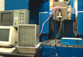
Tapemation uses a MCV 4000 laser calibration system from Optodyne with a dual beam laser head, dual channel processor and squareness optics for running linear, angular (pitch, yaw, straightness, flatness) and squareness calibration.
For the trend in “micro” components, look to the macro world. Manufacturing at conventional scale was used to produce stationary objects first. Only later was it used to make the parts in moving assemblies. In a similar way, the evolution of micro manufacturing is proceeding from stationary objects to the components of micro machines.
But the design and properties of these tiny moving parts are strictly limited. Their production today generally involves a layering process, microlithography. The material choice therefore consists of silicon or sputtered metal, and the geometry is limited to a 2 1/2 D form that can be built by stacking layers. Why can’t the designer instead be allowed to specify a micro component with 3D geometry that is machined from solid steel?


Speed, or the lack of it, accounts for much of the answer. A tiny tool needs a high rpm value in order to realize both an efficient cutting speed and a productive metal removal rate. An analysis of how much speed is needed for effective 3D micro milling recently put the speed requirement at about 500,000 rpm.
That by itself is no big deal. A dentist’s drill can do 300,000 rpm. But a dentist’s drill may also have a runout of 10 microns. In micro milling, that amount of runout is about 10 times what the chip thickness may be.
This comparison with a dental drill comes from John Ziegert, a professor with the University of Florida’s Machine Tool Research Center in Gainesville, Florida. Dr. Ziegert is overseeing the design and construction of a 500,000 rpm spindle that offers the potential to mill steels and comparable metals to produce complex features measured in hundreds of microns. The spindle would use tools 0.010 inch in diameter and smaller that today are typically used only to machine simple features in soft materials such as aluminum, graphite and plastic.
The University is testing the first incarnation of its 500,000-rpm design at this writing. When and if the spindle proves it can cut reliably, it will be sent to Sandia National Laboratories for machining trials. Through its microsystems research program, Sandia has developed the capability to make milling tools as small as 25 microns in diameter. Past experiments with this tooling have been limited to spindles offering no more than 30,000 rpm. That slow speed permitted feed rates best expressed in inches per hour—specifically, just 5 to 14 inches per hour.
Micro Versus Macro
Much of the work of developing the spindle has involved studying the research into micro machining that has already been documented and assimilating the lessons of this earlier work. Dr. Ziegert says two important conclusions of this study describe how micro machining and macro machining differ.
First, the mode of tool failure is different. In conventional-size machining, tools wear out. But when machining with a micro-size tool, tool breakage is the more likely outcome. The small tool tends to reach its bending strength limit well before significant edge wear sets in.
The second difference is that the chip thickness in micro machining typically has to be smaller than the tool's edge radius. This is very different from normal-scale machining, where the chip thickness is many times larger than the edge radius of the tool, even during a light finish pass. If the chip thickness in micro machining was proportionately just as large, the cutting force would easily exceed the bending strength of the tool.
The result of a chip thickness smaller than the edge radius is a pronounced negative rake for the micro milling tool. The effective rake angle may be negative 50 degrees. Or it may be even more extreme than this. Such a large negative rake increases the amount of cutting force the chip generates, which further exaggerates the need for a smaller chip. The resulting chip load is so light, only a very high spindle speed can convert the “ipr” into a productive “ipm.” Dr. Ziegert’s analysis of these problems related to bending strength and chip thickness is what led him to the estimate of 500,000 rpm.
No Toolholder
The University of Florida’s design for a spindle this fast uses the shank of the cutting tool as the spindle shaft. The tool, driven by a speed-increasing friction wheel, rotates faster than any other component of the assembly.
No other solution would have allowed the spindle to achieve the necessary low runout, Dr. Ziegert says. A conventional milling spindle uses a toolholder to make the tool an extension of the main spindle shaft. But no toolholder clamping mechanism—not a collet, not shrink fit—could hold the tiny tool concentrically enough for precise 3D milling in hard metals.
Instead, the tool shank spins alone within a custom air bearing. The spindle that drives the friction wheel runs at about 1/10 the speed of the tool, transmitting 0.01 N-m of torque at 50,000 rpm.
Dr. Ziegert says he can cite one more fundamental difference between micro and macro machining from the university’s own experience. In micro machining, it is impossible for the unassisted eye or ear to determine when a tool has been broken. A tool break at the beginning of an 8-hour cycle might not be discovered until the rest of the 8-hour period had been wasted.
Therefore, one other crucial component of the spindle is a three-axis sensor that continually monitors the machining forces. For a micro machining spindle to perform effectively, it needs a safeguard just to ensure that the tool still remains in the cut.


Related Content

United Machining Solutions' Wire EDM Supports Lights-Out Machining
United Machining Solutions’ Agie Charmilles Cut P 350 Pro features a robust design, the Uniqua human-machine interface and multiple automation options.
Read More
YCM Alliance Five-Axis VMC Enhances Machining Performance
YCM’s RX65+ VMC is engineered for speed, rigidity and accuracy in demanding applications.
Read More
SW North America Open House Showcases Advanced Machining Solutions
SW North America hosts its 2025 Open House at its Michigan headquarters, featuring live demonstrations of the BA 322i and BA Space3 machining centers with a focus on medical and aerospace applications.
Read More
To Understand Machine Speeds, Look Past the Spec Sheet
The real-world behavior and performance of a machine depends on use case much more than the numbers listed on its spec sheet.
Read More