
New to Swiss-Type Turning?
What are some nuances to training a person to effectively operate a Swiss-type lathe? This shop offers some suggestions.

Even a person who is familiar with conventional turning centers can stumble when learning how to operate a Swiss-type lathe with its signature sliding-headstock design.
Six SB-20R machines were purchased to produce this seating component for a new water-dispensing product. Total cycle time with the previous process using two types of machines was 56 seconds. The SB-20Rs machine components complete in 20 seconds.
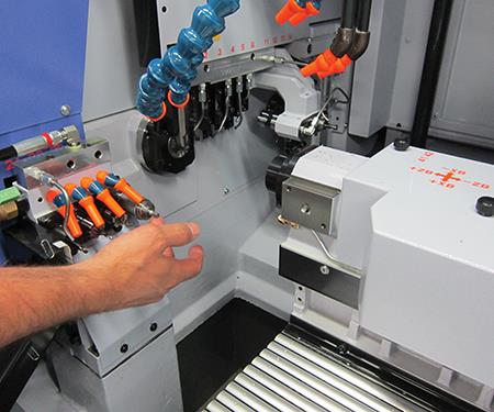
To adjust the guide bushing, operators move the headstock back to access it...

...then use a device with pins similar in function to a spanner wrench to loosen or tighten the bushing.
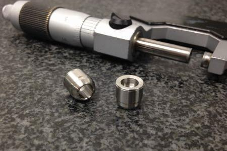
The headstock collet requires tighter adjustment so it can grip the bar when the sliding headstock moves in or out.
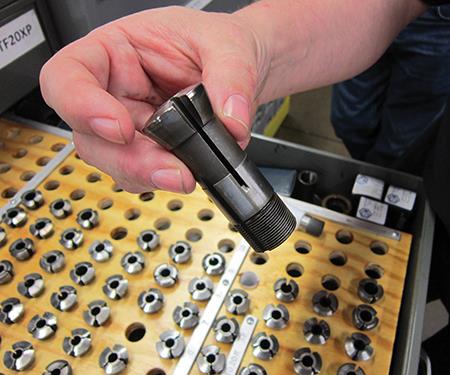
The guide bushing adjustment must be looser so that the bar can pass through to the cutting tool.
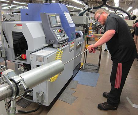
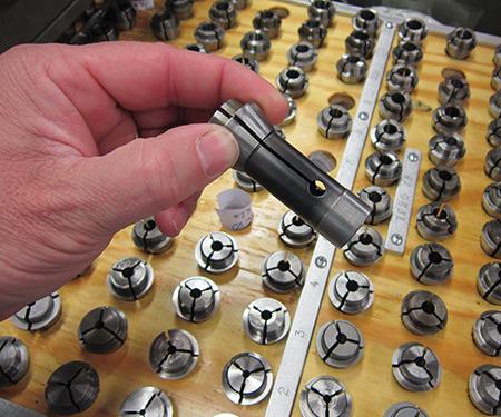
Operators like Brian Converse must be sure the bar does not bind during installation into the bar feeder because that can damage the bar.
Share


Screw machine shops were the first to adopt multifunction CNC Swiss-type lathes. Today, an increasing number of “traditional” shops are considering this machining platform to, in some cases, produce complex parts complete, reducing setups, secondary operations and work-in-process. The goal in using this equipment is to minimize the number of times a part is touched during production.
That said, operators who are unfamiliar with these machines and their signature sliding-headstock design face a bit of a learning curve. This led me to wonder about what specifically needs to be pointed out to a person who either has some experience with conventional turning centers or no machining knowledge whatsoever. In order to get some suggestions, I recently visited Vallorbs, a manufacturing operation in Bird-in-Hand, Pennsylvania, that has a wealth of experience with Swiss-types.


Needles to Nuclear Parts
Kenneth Rinier, general manager, says the business started in the early 1900s and was originally named the Vallorbs Jewel Co. Early on, it specialized in manufacturing jeweled bearings for Swiss watches and the aircraft industry, as well as sapphire phonograph needles. Vallorbs currently produces parts for nuclear, agricultural, medical, aerospace, electronics and instrumentation applications in materials including stainless steel, titanium, Kovar and Inconel 718, as well as fire-Class-D metal zirconium, from which machining produces highly flammable chips.
Vallorbs is part of Valco Companies Inc., which manufactures high-end systems and components for commercial poultry, pig and egg production. Much of Vallorbs’ high-production work is dedicated to machining components for Valco’s products, such as trigger pins for water drinking systems for chickens. Mr. Rinier says the shop machines 600,000 pins per month using cam-actuated multi-spindle machines. The shop also has 40 cam-actuated single-spindle machines and seven 15-year-old CNC Swiss-types for other high-volume jobs. Mr. Rinier refers to those seven as the shop’s “vintage” Swiss-types. That’s because Vallorbs purchased seven new Swiss-types last October, six SB-20R and one SR-20J, from Star CNC Machine Tool.
The six SB-20R machines were purchased to produce a seating component for a new precision feather-action water-dispensing product Valco developed (shown above). The shop originally thought it could produce these components on a several old Acme multi-spindle and Kummer lathes for secondary ops. Total cycle time for a component using this production method was an unacceptable 56 seconds. Mr. Rinier says Star proved its SB-20R could machine components complete in 20 seconds.
Four of those six SB-20Rs have magazine bar loaders. Conversely, the other two and the SR-20J are geared more toward job-shop work and have Super Hydrobar bar feeders from LNS America.
Robert Pitts, primary operations supervisor with more than 30 years of experience in the company’s screw-machine department, says the lower-volume job-shop work the company takes on ranges from 50 to 5,000 pieces. He points to a good example of the advantage the improved capabilities the shop’s new Swiss-types offer in a part for the nuclear industry. This component originally required seven different secondary operations. After initial turning on one of the vintage Swiss-types, the parts then required thread rolling, drilling of several holes, broaching a hex into the head, deburring the hex and deburring the intersection of the holes. Conversely, the new Swiss-type reduced cycle time and minimized scrap while machining each part complete.
But while the Swiss-type platform offers a wide range of capabilities for complex work, the machines still require deft operators to ensure the machining processes proceed as planned. Like many other shops, Vallorbs starts with the basics when training new operators, including instructions on using micrometers, reading prints and so on. However, there are subtle differences in what’s required to run a Swiss-type machine compared to a conventional lathe, so here is what the company also communicates to new operators.
Learn the Swiss-type platform.
Before operating a Swiss-type, it’s important that new personnel understand the sliding-headstock concept and how the machines differ from conventional turning centers. A Swiss-type uses a sliding headstock that feeds barstock through a guide bushing and past a tool during an OD turning operation. The guide bushing offers support for the barstock very near the point of the cut, preventing workpiece distortion. This makes Swiss-types particularly effective for producing long, slender parts. The machines Vallorbs has also have a subspindle to enable backworking operations to be performed on parts after operations on the main spindle are completed.
Mr. Pitts says some operators initially have a tough time understanding tool movements. Many aren’t used to the headstock feeding the bar into the tool, which is unlike conventional turning operations in which the bar is spinning in a fixed position and the tool feeds into it. Plus, these machines are hybrids of sort, because while the main spindle features a sliding headstock, the subspindle for backwork grips parts in its collet like a chucker. Operators making adjustments for backwork need to keep that in mind.
Know the difference between a headstock collet and a guide bushing.
Swiss-types have a revolving collet in the headstock as well as a revolving or stationary guide bushing. The revolving collet must be adjusted tighter to enable it to grip the bar when the sliding headstock moves in or out. However, the guide bushing must be adjusted so it is loose enough to enable the bar to pass through, but not too loose to reduce the bar support needed near the point of the cut. Mr. Pitts says the only real way to learn how to properly adjust the guide bushing is through experience and getting the “feel” of a proper adjustment in which there’s some drag when rotating the bar, but not too much drag. To adjust the guide bushing on the Star machines, operators simply move the headstock back to access the bushing, then use a device similar in function to a spanner wrench with pins that are inserted into the bushing to enable it to be tightened or loosened (see the photos below).
Mr. Pitts typically purchases guide bushings that are 0.001-inch bigger than the bar diameter. That way, an operator will not have to tighten the guide bushing more than 0.005-inch. He believes tightening it any more than that can cause the slots in the guide bushing to close too tightly, which can prevent the necessary lubricating oil from flowing into the bushing.
Measure each bar before installing.
The guide bushing must be loosened each time a remnant is removed so as not to gall the bushing during removal. This means the guide bushing has to be re-adjusted each time a new bar is loaded. Most ground bars Vallorbs uses have a diameter accuracy of ±0.0005 inch, meaning the amount of adjustment can vary from bar to bar. However, Mr. Pitts says that’s not a problem, because an operator needs to re-adjust the guide bushing for each new bar anyway. What is problematic is if the diameter of a bar varies along its length. For example, say there is a section of the bar where the diameter is a few tenths smaller than nominal. This will diminish the support that the guide bushing would otherwise provide, leading to higher runout and concentricity errors. Measuring a bar before installing it into the bar feeder will reveal any diameter deviations. Similarly, diameter deviations discovered with post-machining part measurement can indicate to an operator that the guide bushing adjustment was too loose.
Although installing a new bar into the LNS Super Hydrobar bar feeders is relatively simple, Mr. Pitts gives each operator an instruction sheet outlining all the steps. Essentially, an operator removes the remnant from the machine, then unlocks and swings the bar feeder away from the machine to insert a new bar (see photos on the opposite page). The operator must be sure the bar does not bind during installation because that can damage it. With the bar installed, the bar feeder is pivoted back and locked into operating position. The operator then pushes the bar through the headstock collet to the cutoff position and inputs a cutoff code to part-off the end of the bar. Production can then begin.
Mind the decimals.
More often than not, simply zeroing offsets after changing an insert is all that’s required to start producing good parts again. In some cases though, an operator must input an offset value. New operators sometimes slip up by entering an offset value with the decimal in the wrong position. Mr. Rinier says the control on the new Swiss-types prompts operators to check that the offset value they entered is correct, so that can minimize the chance for the wrong value to be accepted.
Take care when offsetting tools.
Operators of Swiss-types must remember that a single tool might be used to perform a number of different operations. Therefore, adjusting the offset for a tool that’s currently producing an oversized diameter, for instance, might adversely affect subsequent operations the tool performs for that particular job. For example, the adjustment could cause the tool to rough a different diameter too deeply, meaning that for the subsequent finishing pass a tool will be cutting air. Mr. Pitts says operators need to look at the bigger picture and be mindful of every operation tools will perform. Although the part print shows every operation each tool will perform, this concept can still be tough to comprehend for someone who is new to machining.
Operators also must be diligent in examining parts after machining for signs that a tool is wearing. Vallorbs provides eye loops and has optical comparators throughout the shop to enable operators to detect burrs, changes in surface finish, corners that are not crisp, and other indications that a tool is worn and starting to push the material as it cuts.
Know the workpiece material.
Similarly, some materials are harder on tools than others. For example, Mr. Rinier says operators might have to change offsets when running Inconel 718 for every new part, meaning they must dilligently measure each part after machining. This might not be the case when machining less-demanding materials in which offset adjustments might not be needed until a number of parts are completed.
Watch the coolant lines.
After a setup person gets a new job running, he’ll watch to see that the coolant is being directed to the proper location and that chips are being evacuated as they should be. During production, though, it’s possible that an operator could bump a flexible coolant line out of position when changing a tool or insert, for example. Left undetected, this could cause problems such as tool breakage, shortened tool life or poor surface finish.
Get a feel for finishes.
A turned feature looks different than a milled one. Both might have the same finish rating, but the milled surface includes witness marks that turning doesn’t produce. Mr. Pitts says this sometimes takes an operator a little time to appreciate. Similarly, a drilled hole looks different from one that’s been bored. However, if a hole tolerance is loose enough, it might be possible to simply drill the hole and skip the boring operation. All an operator needs to do is check the surface finish specification on the part print whenever they are in doubt.
Vallorbs, call 717-392-3978 or visit vallorbs.com.


Related Content

Ballbar Testing Benefits Low-Volume Manufacturing
Thanks to ballbar testing with a Renishaw QC20-W, the Autodesk Technology Centers now have more confidence in their machine tools.
Read More
Additive/Subtractive Hybrid CNC Machine Tools Continue to Make Gains (Includes Video)
The hybrid machine tool is an idea that continues to advance. Two important developments of recent years expand the possibilities for this platform.
Read More
Orthopedic Event Discusses Manufacturing Strategies
At the seminar, representatives from multiple companies discussed strategies for making orthopedic devices accurately and efficiently.
Read More
4 Tips for Staying Profitable in the Face of Change
After more than 40 years in business, this shop has learned how to adapt to stay profitable.
Read More