
Process Versus Geometry
Most CAM software can be classified as either fundamentally process-based or fundamentally geometry-based. Understanding this often-overlooked distinction can help you find the CAM system that is best for your needs.
Share


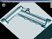
Even though this part has a lot of geometry, it is a process-complex part.
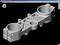
Precisely and cleanly machining the mold cavity's surface geometry makes this relatively small part geometry-complex.
Though it appears that this part contains complex geometry, it is actually better suited to programming on a process-based CAM system.
For a manufacturer that has been manually programming its CNC machine tools, computer-aided manufacturing (CAM) software can provide a technology foundation that allows that company to keep up with the competition. For a company that already uses CAM, upgrading the CAM software can introduce new efficiencies or new capabilities, allowing the company to take on new business. Often a manufacturer will buy new CAM software to get the full benefit of a recently purchased machine tool.
It’s clear that CAM software plays a vital role in today’s manufacturing industry. But as important as CAM software is to a manufacturer’s operation, a fundamental aspect of CAM software is often overlooked during the selection process.


Many shops evaluate CAM software by studying an extensive list of features: how many different ways a line or circle can be constructed; how many different roughing routines are supported; how many different data file formats can be imported. A critical part of the evaluation process then becomes a matter of filling out the evaluation checklist of features for each system being considered and then comparing them to determine which system has more capability. In general, most vendors provide product data sheets that fully itemize the functionality of their CAM software, making filling out the evaluation checklist fairly straightforward (as long as similar terms are used).
Industry analysts do independent reviews of CAM software to assess new versions or capabilities, and some shops rely on these reviews to guide their buying decision. However, these reviews rarely stray far from either an explicit or an implied checklist. Checklists certainly make the job of evaluating software a rational process, but these are relatively low-level evaluations. Before delving into a fine level of detail about features on the checklist, it is important that a basic understanding about CAM system fundamentals be established first.
Two Basic Types
There are two basic types of CAM systems—process-oriented and geometry-oriented.
Process-oriented CAM systems focus on the process aspects of manufacturing engineering, such as efficient use of tooling and machining operations, optimal tool changes, and the control of complex processes. Geometry-oriented CAM systems focus on the geometric aspects of manufacturing engineering, such as handling complex part geometries, dealing with large CAD models, or driving process details through geometric conditions.
These basic orientations influence CAM systems right down to their fundamental system architectures. Because this basic orientation goes to their core, process-oriented CAM systems are capable of handling extremely complex processes, but they maintain a comparatively simple notion of geometry. On the other hand, geometry-oriented CAM systems are capable of handling extremely complex geometries, but they tend to have rather simple process abilities. The inherent ability of each type of system to handle certain kinds of workpieces better than the other aligns each type to specific programming domains.
Process-oriented CAM systems are extremely well suited for production machining work where the geometry may not be the most demanding aspect of the job compared to the overall process complexity and the requirement to optimize the process as much as possible to reduce overall machining time. A good example would be a plate with a considerable number of 2½D pockets and holes. Although this geometry may seem to be complex, it actually isn’t. Instead, the part’s overall process complexity—the pocketing operations and the hole-making operations with all the associated tooling and tool changes—is really the complicated aspect of this part. Creating an NC program that optimally applies the tooling to realize the shortest production time is a process-oriented problem.
Geometry-oriented CAM systems are extremely well suited for mold, tool and die work, where the more challenging aspect of the job is the geometry of the part rather than process optimization, since usually a very limited quantity of parts is being machined. A good example would be the geometry for a complex mold cavity for an injection molded part or the stamping die for a sheet metal automotive panel.
In this situation, the machining process is relatively straightforward, but the geometric aspects are extremely demanding in their exactness and overall extent. The goal here is to create a process that machines an accurate and extremely smooth finish to form the desired part surface—a geometry-oriented problem.
Back To Roots
Whether a CAM system is process-based or geometry-based is often determined by its heritage. The roots of geometry-based CAM systems often can be traced to CAD systems; many were extensions built on top of a CAD system to generate tool path from the CAD system’s geometry. The roots of process-based CAM systems can often be traced back to non-graphical, language-based CNC programming systems; their initial development allowed users to create the CNC program statements in a non-text environment.
Because both systems essentially created M- and G-code output for machine tools, both approaches have been grouped under the label “CNC programming” or “CAM” systems. Over time, the differences between the two types have become blurred. Comparing the systems by feature lists further blurs the basic differences between the systems because feature lists don’t disclose the inherent differences between the two approaches.
CAM buyers who rely upon comparisons of feature lists to guide their purchase decisions run the risk of buying a system whose basic type is not necessarily the best fit for the type of work they do. This mistake is not easy to diagnose. After all, the CAM system selected often appears on paper to be the best collection of functionality. Moreover, most CAM vendors don’t openly declare the type of CAM system they offer.
When difficulties arise after making the wrong choice, it is natural for the buyer to think that the problem is internal, not outward with a basic limitation of the system purchased. So buyers invest a significant amount of additional time and resources trying to get the mismatched system to do a good job on the type of work they do, without realizing that they are attempting to make the software do what it isn’t fundamentally capable of doing.
For example, a user may have a geometry-based CAM system that does an excellent job of cutting the cavity for a mold but can barely handle the task of machining holes for alignment pins or cooling channels in the mold base. Another user may have a process-based CAM system overwhelmed by the task of machining the stamping die for the floor pan of an automobile. Neither situation indicates that the respective systems are badly engineered. Rather, they simply are not set up to do tasks outside what their basic type of system can handle capably.
What’s The Emphasis?
Understanding a CAM system’s basic type reveals the orientation or emphasis of the system’s capabilities. For example, a process-oriented CAM system naturally will tend to focus on process-related capabilities. A well-developed ability to store standardized processes in a knowledge base for reuse later on is something a process-oriented system would be expected to have. The ability to re-order a process sequence to minimize the number of tool changes, or to minimize the overall travel distance when machining a series of holes (the classic “traveling salesman” problem) is also a strength one would expect of a process-oriented CAM system. Associating workpiece geometry, processes and the corresponding tool path (fully regenerating this tool path when either the geometry or the process are changed) is another capability that one would expect with a process-oriented CAM system.
As you might expect, geometry-based CAM systems tend to focus on geometry-related capabilities. The ability to machine multiple, freeform surfaces by either their model or parametric (U, V) space definition is a capability characteristic of a geometry-oriented system. Likewise, the ability to differentiate between nearly vertical walls versus nearly horizontal floors and to adjust automatically the machining parameters to accommodate the two is something to be expected of a geometry-oriented CAM system. The ability to machine a set of surfaces using another set of surfaces to drive along while checking against yet another set of surfaces is an example of relatively complex geometry-oriented functionality.
Having a basic understanding of which type of system a CAM system is provides a better understanding of the type of emphasis the system will have in its overall feature set.
Whether a CAM system is process- or geometry-based influences what classes of machine tools it can support. Process-based CAM systems tend to be more closely associated with standard 2½D milling machines and two-axis turning centers because these machines usually don’t deal with complex geometries. The emphasis here is on process efficiency. Processes such as hole making or tapping/threading are well supported by process-based CAM systems. In a similar fashion, four- and five-axis positioning, multi-part fixturing or tombstone machining usually are addressed best with process-oriented systems because, though geometry does come into play, the optimization of the process across multiple parts is the dominant issue.
Geometry-based CAM systems tend to be more closely associated with full three-axis milling machines, because these machine are more suitable for more complex geometry, especially when machining over multiple surfaces. Similarly, five-axis milling is also very geometry-oriented because of the complex geometric calculations that need to be made not only to locate the tool tip (X, Y, Z), but also to control tool orientation (I, J, K). The ability of geometry-based CAM systems to deal with complex geometries and geometric calculations makes them a good match for these types of machine tools or machining situations.
Multitasking, High Speed Machining
Multitask machining introduces a whole new level of complexity to CNC machine tools and their programming. This class of machine tools features multiple spindles and multiple turrets and tool groups. Tooling can be applied simultaneously to the stock either within one spindle, or across multiple spindles. The normal, single sequence of process operations is radically expanded by multiple “process flows” occurring in parallel. Parallel process flows, which correspond to multiple tools cutting at the same time, often need to be synchronized. Multitasking machine tools are clearly process intensive, thus requiring a process-oriented CAM system to effectively program them.
It is quite feasible to expand a process-oriented CAM system from a sequential, single flow system to a parallel, multi-flow system. The system’s command of process sequence is extended from a single flow to a multiple flow, and the features necessary to manage the flows are added. It is much more difficult to modify a geometry-based CAM system to support the process complexity of a multitask machining center. Currently, programming multitasking machines appears to exceed the capabilities of most geometry-based CAM systems.
Process-oriented and geometry-oriented approaches may overlap one another and address different aspects of the same machining situation, thereby offering different benefits. For example, process-based and geometry-based CAM systems address high speed machining in fundamentally different ways.
A process-based CAM system adjusts the feed rate as a tool approaches sharp corners to avoid overshooting them. The ability to introduce a feed rate adjustment within a stroke is a process capability. On the other hand, a geometry-based system is more likely to handle sharp corners (or any other geometric discontinuity such as connect moves between strokes) by introducing loopbacks, which allow the machine tool to maintain a constant feed rate. The ability to introduce geometric enhancements to a tool path is a geometry capability. Both types offer viable methods to accommodate various high speed machining situations, but their approaches are consistent with their basic style.
What’s Next?
What does the future hold for process-based and geometry-based CAM systems? Over time, as more and more functionality is added to CAM systems, it will become more and more difficult to differentiate the two types of CAM systems. Examining feature lists to discern whether a CAM system is process-based or geometry-based will be increasingly difficult.
Further advances in computer hardware will mask a CAM system’s orientation by evening out differences between them. As more functionality is added, systems will move from a pure type to a blend. Nevertheless, CAM systems will always retain their fundamental character as either process-oriented or geometry-oriented. This bias will continue to influence the CAM system’s ability to handle process-complex or geometry-complex programming tasks. The distinction between this fundamental orientation will still need to be taken into consideration when buying a CAM system.
About the author: John Callen is vice president-marketing at Gibbs and Associates (Moorpark, California). He can be reached at (805) 523-0004.

.png;maxWidth=300;quality=90;format=webp)


Related Content

The Smarter Way to Take Full Control of Your CNC Machine Shop
Designed to bridge the gap between CAM programmers and shop floor operators, SolidShop provides a seamless, real-time solution for managing G-code, tracking production and eliminating costly mistakes.
Read More
Cutting Part Programming Times Through AI
CAM Assist cuts repetition from part programming — early users say it cuts tribal knowledge and could be a useful tool for training new programmers.
Read More
Continuous Improvement and New Functionality Are the Name of the Game
Mastercam 2025 incorporates big advancements and small — all based on customer feedback and the company’s commitment to keeping its signature product best in class.
Read More
Shop Reclaims 10,000 Square Feet with Inventory Management System
Intech Athens’ inventory management system, which includes vertical lift modules from Kardex Remstar and tool management software from ZOLLER, has saved the company time, space and money.
Read More