
Putting the “Feed” in Zero-Defect Through-Feed Grinding
An automated grinding, inspection and packaging cell churns out two fragile automotive parts per second with zero defects.

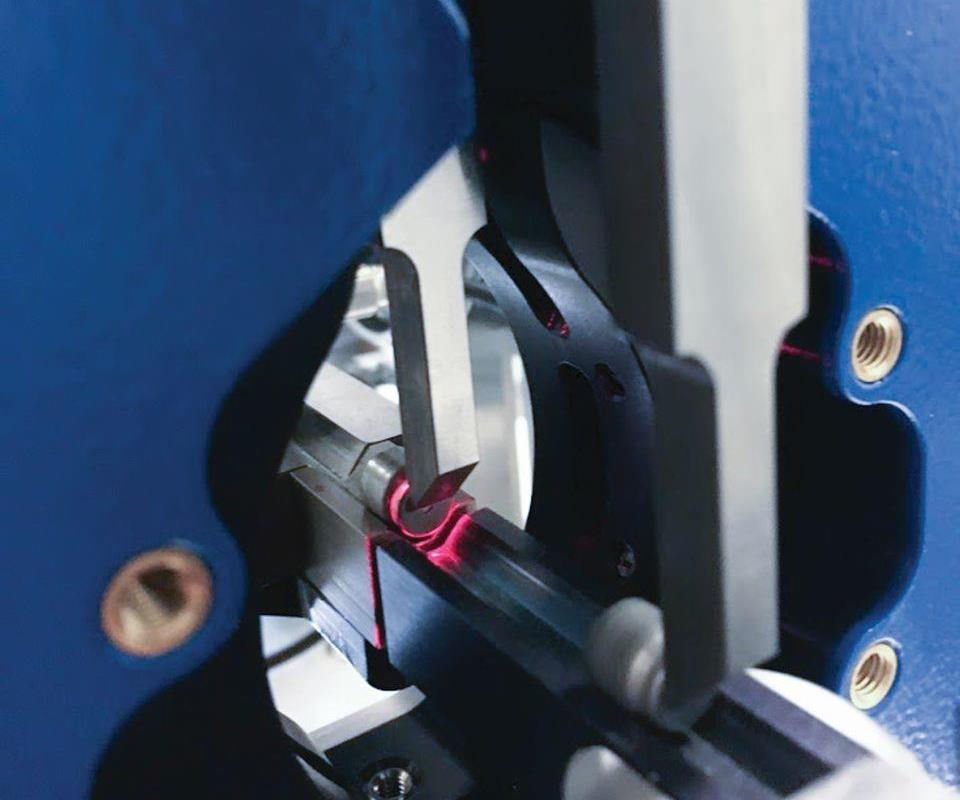
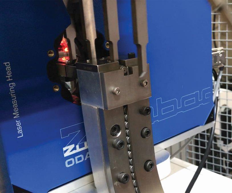
Due to the nature of the parts, rotating them within a laser beam to check for out-of-round geometry was not an option. Instead, the cell employs a device designed for extrusion lines that derives ovality from three distinct diameter measurements taken with three intersecting laser beams. Many of the images in this article are stills from a video of the cell in action. To see it, visit short.mmsonline.com/hifeed.
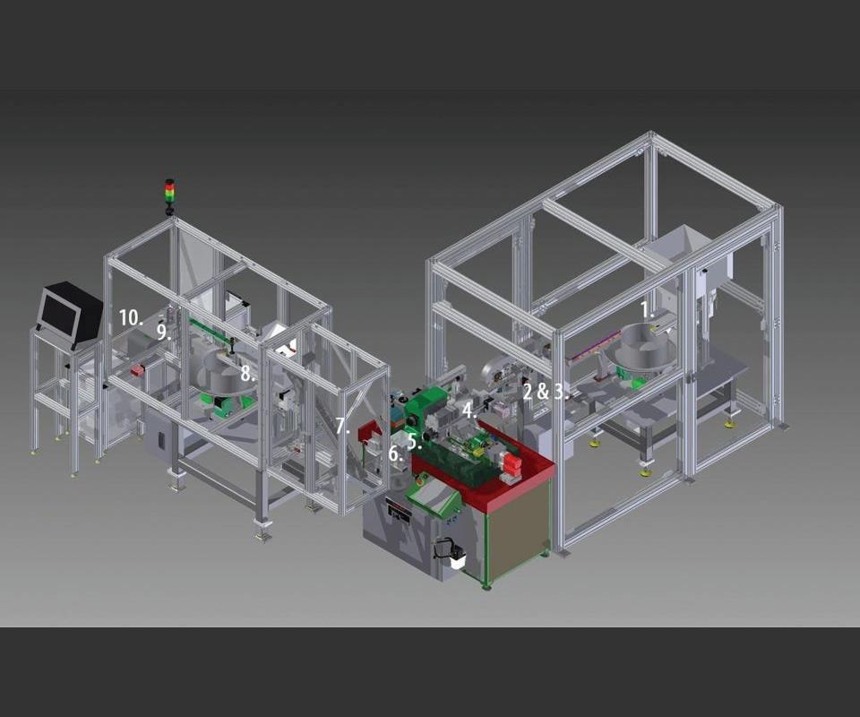
Parts begin their journey in a vibratory bowl feeder (1), then pass through a singulation system (2) and laser and camera inspections (3 and 4) prior to grinding (5). After cleaning (6), they move through another laser diameter inspection (7) that feeds back to the grinder to keep machining on track. A step feed conveyor carries the work to a second vibratory-bowl feeder (8) that feeds parts into two channels. Each stream is broken up again for individual inspections on an eddy current sensor, and good parts drop into a box for shipping (9 & 10).
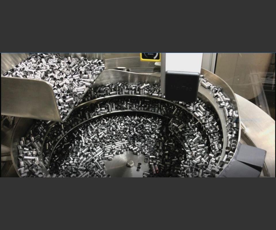
Vibratory-bowl feeders provide an effective means of funneling masses of parts into the singulation systems located before and after the grind.
The singulation system and inverted conveyor occupied a significant amount of the integration team’s time, to the point that engineers began to refer to these units as “the Pez dispenser” and “the porcupine,” respectively. Workpieces that fail pre-grind inspection are diverted down the clear tubes by air blasts before they can enter the grinder (hence the empty conveyor finger visible here).
Here is a closer look at the pre-grind singulation system, conveyor fingers and laser ovality check.
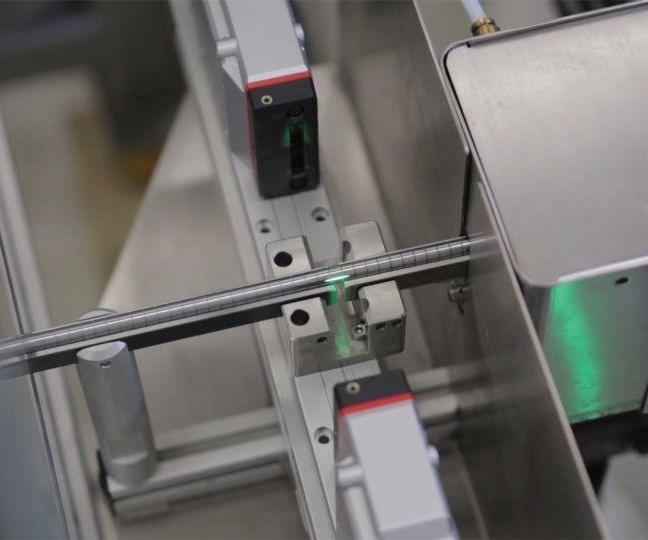
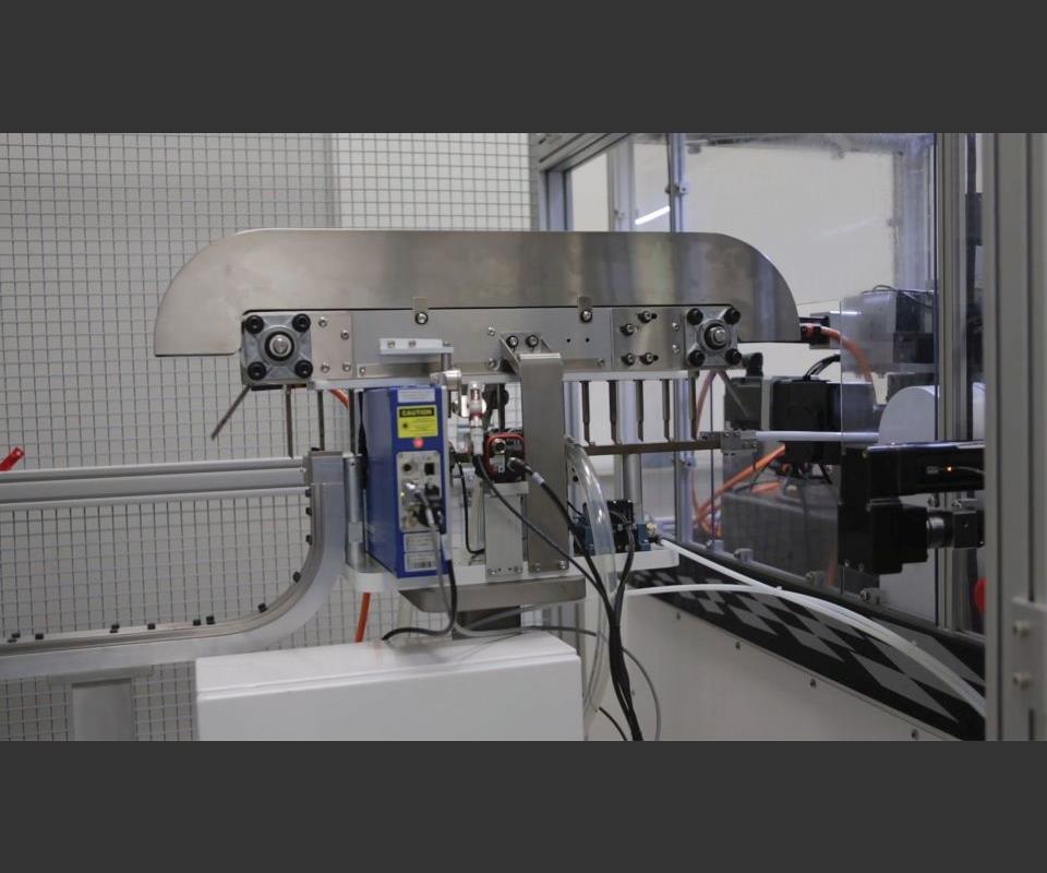
A second laser diameter check after the grind acts as a control on the process, continuously feeding data that’s used for automatic size compensation.
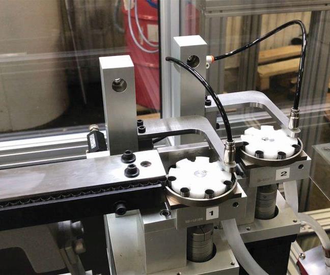
Parts must be separated again and sent through final inspection on two eddy current sensors at a precisely controlled rate. This is accomplished by the cartridges shown here, each dedicated to a separate channel. Every index brings a new part into the cartridge and sends another up the tube toward the sensor.
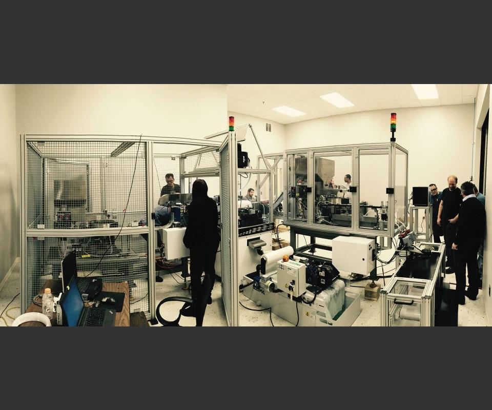
The grinding, inspection and packaging cell is capable of churning out millions of zero-defect parts per year.
Share


Just a sliver. Less than 0.01 inch, in fact. Missing the goal by just a few ten-thousandths of an inch would put the thimble-like steel part out of specification. That is, assuming it hadn’t already been cracked or deformed before it entered the grinder in the first place. Controlling for that possibility would require inspecting every single component on the way in, a challenging proposition with more than 100 parts crossing the machine’s workzone every minute. Of course, the actual machining would require close monitoring and control as well. Given the potential for a single flawed part to relegate thousands to the scrap heap, there would be room for nothing less.
This was the scenario presented to engineers from Glebar, a specialist in turnkey grinding, when they first arrived at their prospective new customer’s facility. Frustrated by quality problems with outside grinding services for a high-volume engine component, the automotive parts supplier had decided to bring the job in house. In addition to being fully automated, the process had to churn out a minimum of two parts per second with zero defects.


The component is designed to improve automobile gas mileage by capping off engine cylinders. The part’s brittleness proved to be a greater challenge than its precision. Measuring 0.25 inch long, it features a slightly flaring, thin-walled open profile that easily cracks under pressure. “It’s a delicate grind, to be sure, but Glebar specializes in such operations,” says company President John Bannayan. Thus, it didn’t take long to identify the compact GT-610 centerless system as the best option for quickly shaving 0.008 inch from the part’s diameter without violating critical tolerances.
However, confidence in a process goes only so far when that process can be sabotaged by problems with incoming workpieces. On this job, heat-treat operations had an unfortunate tendency to deform the cold-drawn steel before it could ever meet the grinding wheel. Front-end quality control became a top priority at the outset. “Garbage in means garbage out,” Mr. Bannayan says.
That’s where things got complicated. The challenge wasn’t so much ensuring perfection, he explains, but ensuring perfection without slowing production. Through-feed grinding at two parts per second is one thing; singling out bulk-loaded workpieces for quality control before sending them hurtling through the machine is quite another. Complicating things even further, parts had to be separated again after the grind for final inspection.
As in any complex automation project, designing a cell to grind and inspect thousands of components per day and millions per year required a great deal of thought, effort, and close, continuous collaboration with the customer. In this case, parts emerge complete and drop into a box, ready for shipping. No human intervention is required beyond basic maintenance and keeping the cell fed with work. As for quality and consistency, a process capability rating of 1.7 Cpk provides the customer (as well as the customer’s customer) with confidence that every part is defect-free and produced according to specifications.
Setting the Pace
The single point of monitoring and control for the entire cell is the grinder’s Beckhoff CX Series motion controller and touchscreen human-machine interface (HMI), which uses Glebar’s own front-end software to interface with all servos, gages, programmable logic controllers (PLCs) and other vital organs of automation. Yet, there’s a mechanical control on this cell, too, one that Mr. Bannayan calls the “pace car” for the entire process: the precision singulation system located immediately before the grinder.
Although this system is the primary constraint on production, it is necessary because the tiny parts are bulk-loaded. The journey begins in a vibratory-bowl feeder that funnels the parts onto a conveyor belt. From there, they move single-file down a narrow trench in a continuous, unbroken stream, the back end of one nestling into the open front end of another. Left this way, they’d be impossible to differentiate from one another during laser and high-speed camera inspections that determine whether they’re suitable for grinding in the first place. “If you have any ovality in that part at all, it’s going to bounce around between the two grinding wheels,” Mr. Bannayan says about the laser system. “It’s either going to be out of tolerance or it’s going to crack or break.” As for the high-speed cameras, “chips and other defects can always cause problems with grinding, causing bad parts in the pipeline. That’s unacceptable.”
The problem was that the most obvious means of separating the parts were unfeasible, at least at breakneck speed, he says. They’re too small and lightweight for pick and place. Anything involving magnets might result in parts sticking together after the grind. The engineering and applications teams considered various types of conveyors, but most threatened to physically impede the path of the laser and camera scans. Even systems without such problems offered no way to guarantee proper part orientation. This is critical because laser measurement works essentially by casting a shadow, one that can obscure out-of-round portions of a part’s profile directly in the path of the beam, Mr. Bannayan explains. Thus, getting a true reading would require either rotating parts within the beam or finding another way. The team chose the latter.
Pez Dispensers and Porcupines
Giving up on the idea of spinning the part within the beam required rethinking the fundamentals of the laser station measurement. With minds open to all possibilities, team members investigated various equipment and processes before settling on a Zumbach ODAC Trio. Designed primarily for extrusion lines, this laser unit required firmware tweaks to work with discrete components. However, these minor adjustments proved a small price to pay for one particularly attractive feature: the ability to measure with three distinct beams that target the same location on the workpiece, but from different vectors. As the part passes through, these beams scan its entire diameter, each taking a different cross section from the same point. The control software derives the extent of any ovality from differences between the three cross-sectional measurements.
The team spent even more time figuring out how to precisely space the incoming parts for inspection (and possible rejection) in the first place. The process begins with pneumatically forcing the single-file line of parts up a vertical shaft. A mechanical stop at the summit brings the topmost part to a halt, and the others pile up beneath. Pushing the topmost part forward releases the stop and allows the next part to rise in its place, “kind of like a Pez dispenser,” Mr. Bannayan notes.
Pushing parts out of the so-called Pez dispenser is a task performed by the “porcupine,” the team’s nickname for the inverted conveyor lining the roof of the track. Downward-protruding fingers sweep in and intercept each individual part from behind. These fingers maintain contact throughout the laser and camera scans until they swing up and out of the way at the end of the conveyor, pushing the parts into the grinder in the process.
The upside-down configuration eliminates the risk of the conveyor’s bulk interfering with the non-contact inspection, Mr. Bannayan says. It also facilitates the use of a V-shaped track that keeps parts perfectly perpendicular to the inspection systems. This would be difficult to accomplish with a flat conveyor, even absent concerns about getting in the way of the laser or cameras.
Although decidedly cleaner, approaching from above came with its own set of challenges, he says. For example, the porcupine’s fingers required multiple design iterations to work properly. The final version of the finger design features a sharp angle on the back face of the tip. This eliminates the risk of the back corner unnecessarily knocking the part when the finger swoops up to begin its next revolution around the conveyor. Fingers are also constructed of heat-treated steel to ensure longevity.
At first, properly timing the conveyor’s rotation and the triggering of the inspections seemed relatively simple. That is, it could be based on known distances between the laser, the cameras, and the air blast that blows rejected parts into a side channel. This might have worked for a slower process. At two parts per second, however, even the slightest, most imperceptible elasticity within the conveyor track or the relatively lengthy fingers becomes a problem, Mr. Bannayan says. Given the fact that one mistimed fire of the laser, camera or air blast can be the difference between success and failure on a batch of thousands, the team opted to actuate these processes via laser sensors from Keyence instead.
Automatic Process Control
Inside the grinder, parts are presented to a wheel that measures 8 5/8 inches wide and 10 inches in diameter. The ability to use such a wide wheel in such a small platform (58 × 32 inches) is one advantage of the GT-610 centerless system, Mr. Bannayan says. Such dimensions make a wheel easy to manipulate during change-overs (which reportedly take only 15 minutes) without sacrificing the ability to remove material as progressively as possible by spreading the grind over more abrasive. He adds that manipulating the wheel is rare, let alone swapping for a new one. During initial testing, the wheel reportedly lasted through 20,000 parts before requiring redressing.
Immediately downstream is another laser diameter inspection. In this case, however, there’s only one beam, and parts aren’t separated out beforehand like at the pre-grind station. After the grind, they tend to nestle back against one another, filing past the laser in a continuous stream as it feeds diameter readings back to the control at a feverish pace of 500 per second.
Singulation is unnecessary at this stage because the post-grind laser system is more about process control than quality control, Mr. Bannayan explains. The continuous stream of diameter data is collected, analyzed and fed back to the grinder’s control for automatic size compensation as the wheel wears. “There’s intelligence behind this data analysis,” he says. “We’re not trying to act on every reading; we’re applying algorithms to filter out peaks, valleys and any anomalies to ensure we’re measuring a certain average that we can control the system with.”
This isn’t to suggest that red flags go ignored. Diameter adjustments are plotted in a line graph on the HMI for easy viewing. If the readings trend too far from nominal, the cell stops. With a single scoop, a diverter arm removes not just the offending part (which can’t be reliably identified at such high speed), but also every part in the stream leading back to the grinder. Once parts are cleared out of the cell, manual inspections weed out any that are truly out of specification, and the operation can continue, defect-free, once the problem can be identified and solved.
The primary challenge in setting up this system was balancing the need to avoid faulty parts and keep the cell running with minimum stoppage, Mr. Bannayan says. A data filter that’s too strict would lead to frequent and unnecessary interruptions, and a filter that’s too lenient would lead to unnecessary risk. Fine-tuning was critical, particularly with a system sensitive enough to pick up contaminants as seemingly insignificant as a drop of coolant. This is also why parts pass through an air-knife cleaning station immediately prior to the laser inspection.
Full Automation, Zero Defects
Any faulty part that makes it through the second laser diameter gage is caught and diverted at the next inspection station. A step conveyor carries parts to a second vibratory bowl feeder that funnels them into an eddy current sensor. Commonly used and specifically suggested by the customer as a means of quality control, these devices use electromagnetic fields within the part to detect cracks, voids or other imperfections.
Two of these devices must operate simultaneously to keep up with the two-part-per-second production rate. To that end, the vibratory bowl feeds parts into two channels, each with a circular cartridge at the end that stops the flow of parts. These cartridges index at a precisely timed rate, with each movement allowing a single part to fit snugly into one of the slots carved into its outer diameter. At the same time, a pneumatic tube opposite the feed sucks another part from its cartridge slot and directs it down a tube into the waiting eddy current sensor. Rejects are diverted, and good parts drop directly into a box. When the count of good parts matches the batch size of 10,000, the first box is conveyed out of the cell for shipping, and a new one shuttles in automatically.
For the customer, the new cell will mean no more manually pushing every part through eddy current and laser inspection to weed out rejects, no more manual boxing (or re-boxing) prior to shipping, and perhaps most importantly, no more surprises or emergencies. For anyone else, this project demonstrates not only the possibilities of modern automation systems, but also the hard work, creativity and expertise they require, even if the specifics of this project are unique to a particular supplier and customer.

.png;maxWidth=300;quality=90;format=webp)


Related Content

Cutting Part Programming Times Through AI
CAM Assist cuts repetition from part programming — early users say it cuts tribal knowledge and could be a useful tool for training new programmers.
Read More
Using Automation to Reduce COGS and Stay Globally Competitive
Decade-long, multiphase automation investments lower operating costs and maintain technology lead in an increasingly competitive global market.
Read More
Studer's Automation, Entry-Level Solutions Take Center Stage
At its 2024 Music Motion Meeting, Studer AG showed off its entry-level line of grinding machines, as well as its newest universal loading system.
Read More
Setting Up the Building Blocks for a Digital Factory
Woodward Inc. spent over a year developing an API to connect machines to its digital factory. Caron Engineering’s MiConnect has cut most of this process while also granting the shop greater access to machine information.
Read More