
Racing to Create Custom Pistons
Laser scanning technology enables this automotive aftermarket company to design and machine custom sets of pistons in short order.

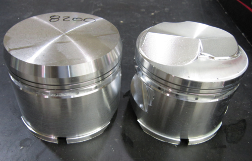
Diamond Racing is able to quickly design custom piston domes engineered to complement an engine builder’s unique combustion chamber shape...
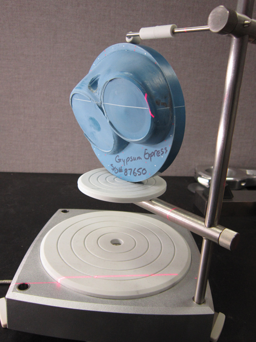
…using this 3D laser scanner from NextEngine.
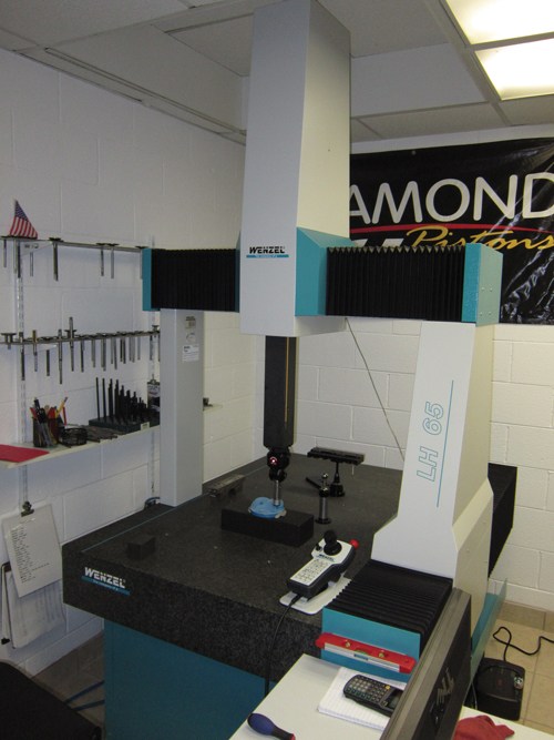
The first step in reverse engineering a combustion chamber mold is to have this Wenzel CMM…
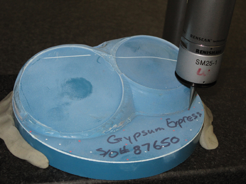
… pick a handful of points to establish plane locations.
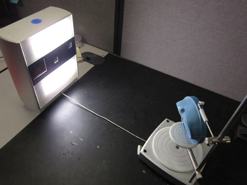
The compact scanning unit takes three images of a combustion chamber mold, and its software accurately stitches the images together to create a 3D mesh model.
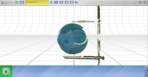
As shown in this image, some portions of a target may be missing in each of the three scans. However, a complete model will be generated after the software combines and aligns the three scans.
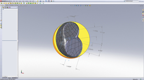
Here is an example of a CAD model of a piston dome created from laser scanning a combustion chamber mold.
Share


For professional racing engine builders, the key to maximizing a power plant’s performance is engineering a combination of components that complement one another. In most cases, this requires either modifying readily available parts or creating custom ones. Off-the-shelf engine components might be fine for builders looking for modest performance gains, but they simply don’t cut it when the goal is to generate significant power.
Builders know that major gains can be realized by improving air flow through an engine. An internal combustion engine is effectively an air pump, so the easier it can “breathe,” the more power it can make. That’s why builders devote so much attention to cylinder head design and, in particular, the shape of combustion chambers and intake and exhaust ports. Builders will manually sculpt, blend and smooth these features until they settle on the organic, one-off shapes that meet the application’s airflow requirements.


To achieve optimal performance, however, a change to one component often requires changes to others. In this case, modifying the combustion chamber means piston geometry must also be customized in order to achieve the desired compression ratio, total combustion chamber volume and other key characteristics a builder desires.
Years ago, builders accomplished this by modifying pistons by hand. Now, new manufacturing and digitizing technologies are enabling aftermarket piston makers to effectively create custom pistons that complement a builder’s unique combustion chamber design. By reverse engineering a combustion chamber’s concave surface, piston designers can create a mating piston dome shape that provides adequate valve clearances as well as offsets to achieve the builder’s performance goals.
One such piston manufacturer, Diamond Racing, has developed a particularly innovative method of creating custom pistons quickly and relatively inexpensively. The Clinton Township, Michigan company combines CMM and laser scanning equipment with CNC machining to produce a set of custom forged pistons in a couple of weeks. That said, the reverse engineering process the company has implemented enables it to offer an expediting service. For a cost, it will design, machine and deliver a set of custom pistons in seven days.
Digitizing Then and Now
Diamond Racing has manufactured racing pistons since 1968. While the company stocks a variety of standard models suitable for a wide range of performance applications, professional engine builders appreciate its ability to deliver custom pistons tailored to their exacting requirements. Jon Kempf, Diamond Racing’s engineering manager and lead piston designer, took me through the process of creating custom pistons during a recent visit.
The design of a custom piston at Diamond Racing involves the creation (and subsequent combination) of CAD models for the bottom portion of the piston as well as its dome. Generating a CAD model of the bottom portion is essentially a template-driven exercise. The company has developed proprietary software that enables designers to choose a style of piston forging and then enter basic information, such as engine bore size, ring groove size, wrist pin diameter and so on, to create the CAD model for the bottom of the piston.
While that process is fairly straightforward, the real trick is modeling the piston dome. That’s because each engine builder’s cylinder head combustion chamber design is a unique, contoured shape.
Diamond Racing previously combined CMM and additive manufacturing technologies to capture these custom shapes. The first step was using the CMM with touch-trigger probe to digitize the surface of either an actual cylinder head combustion chamber or a plastic mold of a combustion chamber. The CMM measured points in 0.025-inch intervals along the entire surface of the combustion chamber, completing its measurements in four to five hours. Then, via an additive process, the CAD model that was derived from the CMM measurement data was used to create a prototype piston layer-by-layer in zircon, a gypsum-based material. Coating the completed prototype in resin made it sturdy enough for turning the piston skirt and machining the wrist pin bore. The customer would then install the completed prototype piston into a mock-up engine where piston dome modifications might be made. If modifications were made, the changes were captured by re-digitizing the prototype on the CMM.
Diamond Racing’s reverse-engineering approach has since been greatly streamlined with the addition of a new Wenzel LH65 CMM and an affordable 3D laser scanner from NextEngine. The current process also starts with either a cylinder head or combustion chamber mold. However, instead of having the CMM digitize an entire combustion chamber surface, the device is used only to determine valve and cylinder bore center points and to establish planes for the engine deck surface and intake and exhaust valve surfaces. The bulk of the reverse engineering work is subsequently done by the 3D laser scanner, which quickly and accurately digitizes the complex, contoured shape.
The scanner consists of two parts: a compact, portable scanning unit and an automated turntable with a parts gripper that rotates the scanning target to capture images of multiple sides. The system measures 3D geometry by projecting an array of laser stripes that bend to fit the shape of the targeted object. As the laser stripes sweep across the target, their shape continues to change. Image sensors built into the scanner record this action, capturing thousands of 3-megapixel photos. The scanner’s software processes these photos and produces a 3D point for each pixel of the captured stripe. In a process called cross-validation, the 3D stripes are compared, and any points that don’t agree across the stripes are dropped. According to NextEngine, cross-validation greatly helps reduce small spikes, “noisy” surfaces and cleanup work to the model. The resulting 3D model has both the shape and visual appearance of the target.
Scanning operations are done on Mr. Kempf’s office desk. A rubber mat on his desk serves two purposes. First, it protects the desk from being nicked by cylinder heads. Second, it features markings that note the field-of-vision distances for operating the scanner, which can be used in macro or wide modes. Mr. Kempf has found that in the wide mode, the optimal distance separating the scanning unit and target is 16 inches, while the macro mode works best at 8 inches. He notes that the wide mode, though slightly less accurate than the macro mode, is better for combustion chamber scanning applications. That’s because portions of the combustion chamber surface are CNC-machined with inherent cusps and ridges. Scanning this type of surface in the macro mode would capture all of those elements. This would require much more smoothing of the resulting CAD model.
To scan a combustion chamber mold, the mold is first installed on the turntable. Using the system’s ScanStudio operating software, the scanning unit takes three separate scan images of the mold (straight-on and rotated at 45 degrees to the left and the right). Total scanning time is approximately 20 minutes.
As shown in one of the photos on the fight, portions of the target may be missing in each of the three scan images. However, combining the three scans results in a complete model. Small dots added to the mold with a marker facilitate the combination and alignment of the three images. These dots appear in the scanning images. Mr. Kempf picks a number of common dots in each of the images, and the ScanStudio software automatically combines the three images into one by aligning them with the reference dots. Afterwards, the software displays alignment accuracy, which must be 0.001-inch or better.
The result is a 3D mesh model of the combustion chamber mold. The mesh surface, which uses tiny polygons to connect the scanned points together in a cohesive shape, is automatically sent to another piece of software called RapidWorks that converts it into a parametric solid model. That model can be automatically exported into SolidWorks (it is also possible to export
parametric solid models using the IGES and STEP file formats, as well as ProE, NX and AutoCAD). At this point, the CAD model of the combustion chamber is modified in SolidWorks to compensate for piston-to-valve clearances and offsets in creating the piston dome model.
Unlike Diamond Racing’s previous CMM, its new Wenzel CMM can create IGES files from the measurement data. Using SolidWorks, this enables the company to compare the initial CMM measurement data of the combustion chamber to the piston model to enable designers to perform volume modeling per the engine builder’s specifications. Once the piston dome model is complete, it is combined with the model of the bottom portion of the piston to create a single solid model.
Finally, A CAM programmer uses the final model to develop tool paths for machining on one of the shop’s Haas VMCs. Cycle times for machining piston domes is approximately 20 minutes per piston.


Related Content

Using Air to Measure Squareness
Though most frequently used for diameter measurements, an air plug and platen can be readily configured to measure perpendicularity.
Read More
The Many Ways of Measuring Thickness
While it may seem to be a straightforward check, there are many approaches to measuring thickness that are determined by the requirements of the part.
Read More
A Balancing Act for Differential Gaging
Differential gaging measures using two devices, which has advantages over standard, comparative measurements using a single sensing head. These include the ability to measure size without regard to position.
Read More
Turning Fixed-Body Plug Gages Inside Out
Fixed-body mechanical plug gages provide fast, high-performance measurement for tight-tolerance holes.
Read MoreRead Next

OEM Tour Video: Lean Manufacturing for Measurement and Metrology
How can a facility that requires manual work for some long-standing parts be made more efficient? Join us as we look inside The L. S. Starrett Company’s headquarters in Athol, Massachusetts, and see how this long-established OEM is updating its processes.
Read More