
Sizing Up The Future
This shop installed a bigger CMM to meet its current needs, but the software that came with it has the shop ready for what lies ahead.

Share


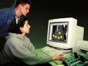
With the new software, visual representation of measurement results gives George Woyansky and his Quality Manager, Jeannine Woyansky, a clear picture of workpiece dimensions in relation to tolerances. The corresponding numerical data can be easily arranged in various formats and exported to spreadsheet, word processing, statistical process control and other software applications for personal computers.

Although the CMM and its DMIS software have proven extremely valuable working with GD&T information conveyed on 2D part drawings, many of the shop's customers are moving to 3D and solids-based part models. Working directly from this CAD data will allow the shop to develop, optimize and verify inspection routines by simulating the CMM, the probe and the workpiece in 3D.
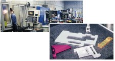
The shop operates a variety of CNC machining centers and CNC turning centers, mostly from Hitachi Seiki. The parts shown at right are typical.
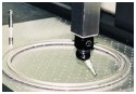
Wonder Machine's new direct computer-controlled CMM allows the shop to inspect larger workpieces such as this aluminum ring for a medical device.
Like all job shops, Wonder Machine Services Inc. strives to provide the services its customers are looking for. That's what job shops are for.
When George Woyansky Sr., started this Cleveland, Ohio, shop in 1976, it offered precision machining services. A single NC "tape" machine was its only manufacturing resource. Today, "precision CNC machining" is still the essence of its business, but along with multi-axis milling and production turning on 10 CNCs, Wonder offers light assembly, engineering, design and building of tooling or fixtures, and other services.


The next generation of Woyanskys are now involved in the ownership and management of the company, assuring that this shop is positioned to stay in business for years to come and that the business will stay in the family, too. Mr. Woyansky's son, George Jr., is now vice president. His wife, Jeannine, is quality manager. Both have engineering degrees. One other daughter is also part of the company. With the long term growth and continued prosperity of the company in mind, the Woyanskys are careful to evaluate present as well as future equipment and technology needs.
"We can't look just at the equipment required for today," says George Woyansky Jr. "We have to think about tomorrow and anticipate our requirements. We have to see where our customers are going and stay a step ahead of them."
New CMM
A good case in point is a new coordinate measuring machine (CMM) the company installed about a year ago. The immediate need for this CMM sprang from a customer's requirement for 100-percent inspection of a ring-shaped part about 24 inches in diameter. The company began handling more workpieces of this size because its newest vertical machining center is also its largest. With travels of 80 by 33 by 42 inches, this machine allows the shop to process larger workpieces than it formerly could. The ring-shaped part was one of the first jobs the shop had attracted with the new, larger machine.
Unfortunately, the rings were too big to fit on the table of the shop's original CMM, a manual machine purchased about seven years ago. But in the search for a larger model, it quickly became clear that a new generation of CMM software also had to be considered.
"The capacity of our old CMM wasn't its only limitation," recalls Mr. Woyansky. "It was a manually operated model, so it was slow compared to computer-driven models. And different operators got different results because of variations in how they moved the probe or how fast they let the probe strike the part. The software we used to record and analyze measurement data was also limited. It didn't have as much memory as we wanted and it was nearly impossible to recall inspection results for further analysis."
In fact, the search for a new CMM soon settled into a decision about who had the software that was right for this shop. After looking at several CMMs and the software packages which came with them, the shop soon determined that software would have to be DMIS-based and use the Windows operating system.
DMIS
DMIS (Dimensional Measurement Interface Standard) is a national standard for the two-way communication of inspection data between computer systems and inspection equipment. This standard was developed about 13 years ago by sophisticated CMM users and major CMM manufacturers so that files could be transferred to or from computer-aided design systems and CMMs, without translating or reformatting the data. At the time, no such standard existed.
Most CMMs required that inspection routines be formatted in a certain way. Because each type or brand of CMM had its own format, CAD vendors offering software for CMM programming had to develop many translators to format inspection routines properly. And once formatted, the CMM program could not be used to drive any other computerized CMM. Likewise, inspection data from the CMM had to be formatted in a certain way for a CAD system to read and interpret the results of an inspection routine.
DMIS was developed to get around these proprietary interfaces. DMIS provides file transfer capability independent of CAD and CMM vendors. DMIS establishes a readable and writeable vocabulary of terms, set out in a neutral format, for preparing inspection programs and inspection results.
DMIS 3.0 (ANSI/CAM-I 101-1995) is the latest version of the standard. Although DMIS is gaining acceptance among CMM builders, CMM users and CAD vendors, it has met some resistance in the marketplace. Some CMM builders have been reluctant to abandon their proprietary programming languages in favor of DMIS. The DMIS language itself is powerful but complex. Using it in its native text form requires considerable programming skill.
"We insisted on a DMIS-based software system because it gives us the most flexibility," says Mr. Woyansky. "Many of our customers have CMMs and we wanted to be sure our measurement routines and resulting data are compatible with what our customers are doing. For example, they can take our programs and use them to verify our inspection techniques and methods at their facilities, using their CCMs." This capability helps resolve disputes about inspection results.
"Most of all, we know our customers will soon be asking us to work directly from 3D or solids-based part models created on their CAD systems. We are already exchanging drawings in DXF or IGES formats, often via e-mail on the Internet," Mr. Woyansky goes on to say. "DMIS is the key to having the same exchangeability when we begin sharing inspection data based on 3D CAD models.
Windows
Windows is the other feature that Mr. Woyansky considered essential to the company's selection of CMM software. "All of our office software is Windows-based," Mr. Woyansky explains, "So we are familiar with standard Windows features and functionality."
One of the strengths of Windows is that it allows various software applications to share information readily. In Windows, for example, a file created in word processing can insert data created in a spreadsheet application and vice versa. Files can be attached to e-mail messages and transmitted directly to or from customers. "We wanted to be able to take inspection data and use it in the same way we use other file types created in Windows," Mr. Woyansky says.
Another concern was how the software would be supported and updated. Because Windows is so widely used, software suppliers have a large pool of development talent to draw from. This makes it easier for suppliers to support and maintain their Windows offerings.
Icons
A few companies offer DMIS-based software for CMMs, and several others comply with DMIS by providing a translator that converts DMIS into the proprietary language used by their systems. According to Mr. Woyansky, the shop looked into all available DMIS-based software. The one that it liked best was Virtual DMIS from International Metrology Systems (IMS) of Livonia, Michigan. This software, which uses DMIS without translation, was included with the new Merlin CMM that was purchased from IMS.
Virtual DMIS runs on a 32-bit Windows 98 or NT platform. Wonder Machine has this software installed on a Gateway 2000 Pentium II-333 that is located in its metrology room and linked to the shop's Novell-based local area network.
What appealed to this shop was how Virtual DMIS made full use of Windows functionality. Mr. Woyansky explains: "We knew this software was developed in and for Windows. It wasn't a DOS-based system redesigned or recompiled for Windows. You can tell by how it makes full use of toolbars, pull down menus, drop-and-drag capability, and other graphical programming features."
Mr. Woyansky was particularly impressed with this software's use of icons, easily recognizable picture symbols that represent basic geometric shapes or measurement activities. Pointing the cursor on an icon and clicking the mouse button activates the feature or calls up the appropriate menu box prompting the user for selections or values to be entered.
"It's highly intuitive," reports Mr. Woyansky, "especially for someone familiar with metrology. You can readily figure out what the system is asking for and what it is doing with the user's input."
The DMIS-text based programming language is hidden behind this logical sequence of icons in the user interface. The underlying DMIS process commands or geometry definitions represented by the icons can be called up by clicking on the icon, making the full text available for editing by those experienced with the DMIS language, adding to the flexibility of the system. However, this step is not required to produce fully functional programs and routines.
Mr. Woyansky was also gratified to see that IMS continues to add and refine features. Patches and updates are posted on the company's Web site for immediate downloading.
On the perceived strengths of this DMIS-based software, the shop decided to acquire the Merlin CMM from IMS. The new machine was installed in April, 1998, after the shop finished constructing a climate-controlled room adjacent to its existing inspection lab.
A 3D Digitizing Stylus
The new CMM has a measuring envelope of 750 by 1100 by 750 mm (30 by 44 by 30 inches). Its stated volumetric accuracy is 3 microns. The Merlin is produced in some 22 model sizes; the machine at Wonder Machine is one of the smaller versions. Nevertheless, it is large enough to accommodate almost all of the work-piece configurations produced in this shop.
"We found several comparable CMMs in the size range we needed and all of them represented a good value," notes Mr. Woyansky. "Different manufacturers favor certain design elements over others, but we discovered that error mapping and electronic compensation tend to make the differences in mechanical construction less important, so it was fairly easy for us to decide on the CMM hardware in this case."
Mr. Woyansky admits that he tends to view a CMM as a "glorified 3D digitizing stylus." The distinguishing characteristic is the flexibility of the CMM's software, he feels, rather than a particular configuration or mechanical structure.
Not that the shop was indifferent to the characteristics of the new CMM. With his background in engineering, Mr. Woyansky takes a keen interest in these matters and looks for innovations. One feature that distinguishes larger models of the Merlin, for example, is the use of 0.1 micron resolution scales on both sides of the table axis. A patented design feature allows the controller to detect and adjust for any lag between the motorized and non-motorized columns, contributing to the CMM's overall accuracy without adding complexity or substantial cost.
A Measurable Difference
The new CMM and software have made an immediate difference at Wonder Machine. For starters, the shop can now inspect the large ring-shaped part that initiated the move to the upgraded inspection equipment. "We have been making this part for one of our major customers over the past four years," Mr. Woyansky explains. This flat, thin ring is for a medical instrument. Pressed into a ring are more than a dozen pins, close-toleranced at a projected zone above the part surface. "With our old CMM, we had no way of measuring the part completely in one setup, so it was impossible to be sure the part was correct in all aspects. We had a go/no-go gage, but the gage could not tell us where the ring might be out of tolerance, if anywhere." The customer, hpwever, had the capability to inspect the parts, and did make occasional returns.
"These days, if a customer is telling you your parts are unacceptable, you fix the problem or you lose the work. Now, we put the part on the table of the new CMM, let it run, and the machine provides a report on what dimensions are in tolerance and what are out and by how much, and how to adjust our machining to bring it in tolerance," he says.
In addition to this workpiece, the shop has programmed many other workpieces in the first few months the CMM has been in place. The shop did not need to hire a CMM programmer or pull the CNC programmer away from his regular duties. Jeannine Woyansky, the shop's quality manager, now handles most of the CMM programming.
"Jeannine operated the manual CMM but had never programmed a machine before, had no experience programming a CMM, and was a bit intimidated by the DCC CMM—at first. But after a couple of months, she had programmed 30 parts on the Merlin with its Virtual DMIS software," Mr. Woyansky reports.
Although the shop anticipates using the CAD-in, CAD-out capability of the software soon, so far it has worked from part prints, which are often delivered electronically via e-mail or on a disk. The geometric dimensioning and tolerancing (GD&T) noted on the prints is all the shop needs to develop the appropriate inspection routines.
Typically, a part is placed on the CMM and clamped to the base. The shop machined its own subplate with a large array of threaded holes to simplify clamping. The probe stylus is moved manually, via joystick control, to touch on the features that must be inspected. The system recognizes what kind of feature is being measured (plane, cylinder, line). The user then can add GD&T information as provided on the print. The system automatically compares these values with actual measurement points and calculates whether the feature is in tolerance or out (and by how much).
Other features can be measured in turn for a complete inspection. To create a program to inspect additional parts under computer control, the software replays the same steps, moving the probe in up to five axes. Running inspection programs in the direct computer controlled (DCC) mode is considerably faster than manual inspection. Experience at Wonder Machine has shown it to be up to 80 percent faster.
Results are shown graphically on the color computer screen and paper copies can be printed instantly when a color printer is attached to the PC. This "visualization" is a very valuable feature, Mr. Woyansky claims. "We can see at a glance whether we have a good part or not." The software allows graphical reporting with feature labeling so that customers can see how the part was inspected, even if they are not present during inspection, he adds.
For the future, the CMM's capability to read CAD files and be programmed directly from CAD-file data will give Wonder Machine a competitive edge, Mr. Woyansky believes. For example, Virtual DMIS can be used off-line at another PC to generate programs for workpieces. The software represents a true virtual machine—the machine, probe head, stylus, and any other additional hardware is realistically modeled and shown to the user.
The 3D representation of the workpiece can be displayed on the table of the virtual CMM and the simulated probe can be manipulated in the teach mode to create an inspection routine. Programs generated off-line can be sent to the CMM's host computer for later use. In this way, inspection programs and procedures can be written before the parts are machined. When the part is ultimately set up on a CNC machine, there will be little downtime waiting for first piece inspection because the CMM program is ready to go. The CNC operator will get a printout showing what features need adjustment and how much adjustment is necessary. Mr. Woyansky sums it up: "After adjustments are made, the operator can make another part, verify that the adjustments were correct, and be in production—all within a matter of a few minutes."
Brave Move
Wonder Machine's investment in its new CMM and CMM software was about what the shop could have expected to pay for a new mid-range machining center. For a 20-person shop such as this, the decision to buy the CMM was a major commitment. As Mr. Woyansky Sr., pointed out to his son early in the discussion about acquiring a new CMM, the CMM "doesn't make chips."
In essence, Mr. Woyansky Jr.'s reply was that the CMM "makes sure the chips we make are right ones." And that's how the shop has come to regard the CMM. It enhances the productive capacity of every other machine on the shop floor. Lathes and mills may make the parts, but the CMM verifies that customers are getting exactly the parts they ask for, with the documentation to prove it.
Says Mr. Woyansky Jr., "Customers are every bit as concerned about how we are checking their parts as they are about how we are making those parts. We believe that their confidence in our inspection capabilities is essential to keeping them as customers. And they can see that our inspection capabilities are ready to grow right along with them."


Related Content

Using Digital Tap Testing to Measure Machining Dynamics
Tool-toolholder-spindle-machine combinations each have a unique vibration response. We can measure the response by tap testing, but we can also model it.
Read More
Machined Part Geometry Measurement
Uncertain about uncertainty? Having trouble remembering the difference between accuracy and precision? Read on to review key metrology terms relevant to the ISO Guide to the Expression of Uncertainty in Measurement (ISO GUM).
Read More
Turning Fixed-Body Plug Gages Inside Out
Fixed-body mechanical plug gages provide fast, high-performance measurement for tight-tolerance holes.
Read More
Ballbar Testing Benefits Low-Volume Manufacturing
Thanks to ballbar testing with a Renishaw QC20-W, the Autodesk Technology Centers now have more confidence in their machine tools.
Read MoreRead Next

OEM Tour Video: Lean Manufacturing for Measurement and Metrology
How can a facility that requires manual work for some long-standing parts be made more efficient? Join us as we look inside The L. S. Starrett Company’s headquarters in Athol, Massachusetts, and see how this long-established OEM is updating its processes.
Read More