
Surface Finish: A Machinist's Tool. A Design Necessity.
Simple "roughness" measurements remain useful in the increasingly stringent world of surface finish specifications. Here's a look at why surface measurement is important and how to use sophisticated portable gages to perform inspections on the shop floor.
Share


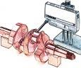
Fig. 2 - The Rk family of parameters describes multifunctional surfaces, such as cylinder walls. On the illustration, the section on the left shows the surface after initial rough cutting. Plaueau honing knocks off the tops of the peaks, as shown on the right. In operation, this surface has sufficient area to promote piston compression, with enough pockets to hold lubricating oil.

The Ra parameter measures average roughness. It is not sensitive to occasional spikes and gouges. On the other hand, the Rmax parameter is designed to detect these anomalies. The two surfaces shown here have nearly identical Ra values but very different Rmax values.
Low-cost, compact battery-operated roughness gages have transformed shopfloor acquisition of surface measurement data. Included in this article are several examples of how these gages are finding wide application on shop floors.
Surface finish, or texture, can be viewed from two very different perspectives. From the machinist's point of view, texture is a result of the manufacturing process. By altering the process, the texture can be changed. From the part designer's point of view, surface finish is a condition that affects the functionality of the part to which it applies. By changing the surface finish specification, the part's functionality can be altered—and hopefully, improved.
Bridging the gap between these two perspectives is the manufacturing engineer, who must determine how the machinist is to produce the surface finish specified by the design engineer. The methods one chooses to measure surface finish, therefore, depend upon perspective, and upon what one hopes to achieve.


What Is Surface Texture?
Turning, milling, grinding and all other machining processes impose characteristic irregularities on a part's surface. Additional factors such as cutting tool selection, machine tool condition, speeds, feeds, vibration and other environmental influences further influence these irregularities.
Texture consists of the peaks and valleys that make up a surface and their direction on the surface. On analysis, texture can be broken down into three components: roughness, waviness, and form.
Roughness is essentially synonymous with tool marks. Every pass of a cutting tool leaves a groove of some width and depth. In the case of grinding, the individual abrasive granules on the wheel constitute millions of tiny cutting tools, each of which leaves a mark on the surface.
Waviness is the result of small fluctuations in the distance between the cutting tool and the workpiece during machining. These changes are caused by cutting tool instability and by vibration, several sources of which affect the stability of every machine tool. Some of these sources are external and sporadic—for example, a passing forklift, and the operation of other machines on the shop floor. Other vibration sources are internal, such as worn spindle bearings, power motor vibration, and so on.
Assuming that the part is nominally straight and/or flat, errors of form are due to a lack of straightness or flatness in the machine tool's ways. This is a highly repeatable type of irregularity, as the machine will always follow the same out-of-straight path.
All three surface finish components exist simultaneously, superimposed over one another. In many cases it is desirable to examine each condition independently. We approach this problem by making the assumption—a correct one, in most cases—that roughness has a shorter wavelength than waviness, which in turn has a shorter wavelength than does form.
Gages separate surface finish components using discrete units of length, called cutoffs. The length of the cutoff selected and implemented by various electrical filtering techniques permits the measurement of roughness by itself, waviness by itself, or "total profile," which combines roughness, waviness and form.
For parts produced by modern machine tools at typical speeds and feeds, roughness may be defined, for example, as any irregularity with a wavelength shorter than 0.030 inch; waviness as between 0.030 inch and 0.300 inch, and form errors as having wavelengths greater than 0.300 inch. These figures are quite flexible, and standards exist for roughness measurements with wavelengths from below 0.003 inch and up to 1 inch.
Surface finish tends to be a stable condition; it should not change from part to part, unless process conditions change. Manufacturing engineers, in fact, can generally predict the surface finish that a process will generate, given a known material, machine tool, cutting tool, coolant, speed, feed rate, and depth of cut. For this reason, surface finish measurements have historically been used primarily as a means of monitoring the stability of manufacturing processes. By taking an occasional measurement, a machinist can establish that the entire process is running as it should.
If the measurement changes, it is a signal that some element of the process has changed significantly—perhaps the cutting tool has reached its wear limits, the coolant needs changing, or a new source of vibration has arisen. By examining roughness, waviness, or total profile separately, machinists can narrow the search for sources of error, and take effective action to reduce or eliminate them.
Parameters
Parameters are the quantitative methods used to describe and compare surface characteristics. These are defined by the algorithms that are used to turn raw measurement data into a numerical value. Although more than 100 parameters exist, machinists have traditionally relied upon just one or two parameters.
Currently, Ra, or average roughness, is the parameter most widely specified and measured. The algorithm for Ra calculates the average height of the entire surface, within the sampling length, from the mean line. It serves as an effective means of monitoring process stability, which explains why it is the predominant parameter in use today (see Figure 1).
Of more than a dozen roughness parameters specified by ASME in Standard B46.1-1995, two others that are widely used on the shop floor are Rmax and Rz. Rmax measures the vertical distance from the highest peak to the lowest valley within five sampling lengths, and selects the largest of the five values. It is, therefore, very sensitive to anomalies such as scratches and burrs on the part's surface, and specifically useful for inspecting for these conditions. But because a single scratch or burr is often not the result of a symptomatic problem in the manufacturing process, this parameter is not so useful for monitoring process stability. On the other hand, Ra, as an averaging function, is fairly insensitive to occasional anomalies, and is therefore not useful to detect the presence of these features.
Rz is widely used in Germany and elsewhere in Europe, in preference to Ra. Like Rmax, Rz is based on the evaluation of five sampling lengths. But instead of selecting the largest peak-to-valley distance of the five, it averages the five values.
Design And Engineering Influences
Thus, even within the single component of roughness, the specification of surface finish goes far beyond the notion of a simple smooth/rough continuum. Through parameters, surfaces can be defined and described in great detail, and engineers have made correlations between parameters and part performance under various conditions.
In some applications, a single scratch may render a part unacceptable from a design-engineering point of view, regardless of how fine its average roughness value. These same considerations apply to the multiple parameters for waviness and total profile.
When a design engineer specifies a surface finish parameter and value, therefore, he must do so with an understanding of how they will affect the part's performance. Selecting the ideal parameter(s) for a given application is somewhat complicated by the great number of parameters in existence, but most of these have limited applications. The majority of applications can be successfully specified using a few well-known parameters.
Smoother, of course, is not always better. There are obvious economic benefits to machining parts as quickly as possible, and to minimizing the amount of secondary work performed. Additionally, there are applications in which a certain degree of roughness enhances functionality, and specifications may specify minimum as well as maximum roughness values. Having some definite roughness to the surface, for example, often enhances adhesion of paint or other coatings.
Some parts that perform multiple functions require complex surfaces to perform optimally. Engine cylinder walls, for example, must be smooth enough to provide a good sealing surface for the piston rings, to promote compression and prevent blow-by. At the same time, they must have "pockets" of sufficient size, number, and distribution, to hold lubricating oil. The Rk family of parameters was developed to describe such complex, multifunctional surfaces. This is an example of the parameters that were developed as design, rather than inspection, tools.
Once a surface has been defined and specified, the manufacturing engineer must determine how to produce it reliably and cost-effectively. In the case of surfaces specified only by the Ra parameter, this is usually quite easy, because the actual shape of the surface can vary considerably and still meet a given Ra value. Finer Ra values can be achieved by many alternate approaches, including slowing the speeds or feeds, making shallower cuts, or following the primary cutting process with a secondary process such as fine-grinding, honing, lapping, and so on. If Ra is the only parameter specified, the manufacturing engineer can choose whichever approach he determines is the most economical and efficient.
But where Ra is strictly a quantitative parameter, the Rk parameters are both quantitative and qualitative, in that they define the shape of the surface. The manufacturing engineer is faced with a more complex task. In the case of the cylinder wall described above, the desired surface requires two-step processing, at minimum. The first step, which may be boring, grinding, or rough honing, produces a relatively rough surface, with many prominent peaks and valleys. The second step, plateau honing, knocks the tops off the peaks, but does not extend to the bottoms of the valleys, leaving a mainly smooth surface with a number of oil pockets (see Figure 2).
Inspection
After the part has been designed and manufactured, it must, of course, be inspected. For surfaces specified only by a roughness parameter, this is a simple matter. Pocket-sized, battery-powered gages that offer a small number of roughness parameters are available at low cost (below $2,000), are extremely easy to use, and can be very flexible in application. (See setup boxes.)
More complex parameters require full-featured instruments that are run by computers, and these devices may cost over $10,000. Some of these surface analysis systems are hardened for shopfloor use, and recent advances in software have made even complex measurements relatively easy to perform.
Existing standards are written around the use of instruments that measure part texture by moving a stylus in a straight line across the surface, and by monitoring the vertical movement of the stylus. Generally, the less expensive stylus-type gages that measure only roughness use the surface of the part itself as a reference. These are called skidded gages. In contrast, the full-featured instruments incorporate a precision internal reference surface, which enables them to measure waviness and total profile in addition to roughness. These are called skidless gages.
Traditional stylus-type inspection is not feasible in all instances, however. Gold-plated surfaces, for example, may be scratched by the stylus. Some high-speed or continuous manufacturing processes require faster throughput than stylus instruments allow. And some design applications require analysis of the surface over an area rather than in a straight line. For such applications, instruments using optical and other non-contact methods, or special area-measuring stylus methods, are available. These are generally quite expensive, however, and standards regulating their performance are still under development, so their use is generally restricted to applications in which traditional stylus methods are impractical.
Inexpensive, compact "roughness" gages, however, often retain their traditional utility, even where more complex parameters are specified. A shop may maintain one skidless gage for manufacturing engineering and quality assurance purposes, while making several of the more economical skidded gages readily available to machinists. Once the process is established and confirmed on the skidless gage, machinists use the skidded gages to measure parts for Ra or another roughness parameter, strictly as a means of ensuring process stability. This often represents a practical approach to meeting surface finish specifications.


Related Content

A 100-Year-Old Measurement Tool That is Still Used Today
The reed mechanism was a breakthrough in high-precision measurement and is still used today for sub-micron or even nanometer resolution applications.
Read More
Machined Part Geometry Measurement
Uncertain about uncertainty? Having trouble remembering the difference between accuracy and precision? Read on to review key metrology terms relevant to the ISO Guide to the Expression of Uncertainty in Measurement (ISO GUM).
Read More
Ballbar Testing Benefits Low-Volume Manufacturing
Thanks to ballbar testing with a Renishaw QC20-W, the Autodesk Technology Centers now have more confidence in their machine tools.
Read More
Using Air to Measure Squareness
Though most frequently used for diameter measurements, an air plug and platen can be readily configured to measure perpendicularity.
Read More