
The Versatility of Snap Gages
The many design modifications available in snap gages enables them to measure some of the most difficult dimensions, right at the point of manufacture.

Share


Insert a workpiece into a snap gage and you will understand how these extremely effective, fairly simple tools for checking precision ODs got their name. You have to push deliberately to get the part past the leading edges of the anvils, but once you have overcome the gaging force, the part slips back against the backstop, contacting it with a good, healthy “snap.”
Snap gages are handheld to measure workpiece ODs on the machine, or they can be mounted on stands for use with small parts. The heart of the tool is a simple C-frame casting, and measurements rely on a direct, in-line, 1:1 transfer of motion. These factors make snap gages simple, robust, reliable and inexpensive.


The earliest snap gages of the fixed, or go/no-go, variety did the job well enough, and thousands are still in use. However, fixed gages did not provide the measurement data so often required for monitoring the manufacturing process. Adjustable snap gages incorporate a settable upper anvil with an indicating readout. Indicating snap gages are able to measure an indicator’s limits of resolution, and because they are comparative gages (they read to zero), they give the user valuable information about machining process.
Before selecting and using an adjustable snap gage, users must decide what feature on the OD they are going to measure. This information is critical in deciding what type of anvils to use on the snap gage.
Two flat anvils are the most common style for adjustable snap gages. These anvils show the effective, or maximum, OD of the part being measured. Also, when looking for the effective size of a shaft that must mate with a bore, flat anvils are typically the answer. They will show the maximum OD without picking up surface depressions that, within limits, are not likely to matter. As a result, exploration of the shaft need not be complex.
Snap gages with flat anvils provide other benefits as a result of the gage's line-to-line contact with the work (see diagram).

Flat anvil snap gages can produce reliable results with a relatively inexperienced operator since the two flat anvils tend to seat the gage positively on the work. The relatively large restoring force of the two flat anvils tends to overcome any tilt applied to the gage by the operator. While this seating ability becomes less as the work diameter increases, it is effective for the large majority of work sizes for which indicating snap gages are used. This is one of the key points in selecting a snap gage for use at the point of manufacture — ease of use and little operator influence result in more reliable measurement results.
When two flat anvils are used, backstop adjustment is not critical. As long as the work is located between the two broad measuring surfaces, a reading of the true diameter will be obtained.
Of course, only two flat anvils will measure right up next to a shoulder.
With a flat anvil snap gage, as with any other gage, there are fewer critical factors involved when you set the gage with a master the same shape as the workpiece. This establishes the same conditions of contact in both instances.
However, not all parts have long, continuous diameters. For this reason, a variety of snap anvils are available to broaden the scope of snap-gage applications. Here is a small sampling of the many modifications possible in snap gaging:
Anvils may be straddle milled to provide two narrow rectangular measuring surfaces for gaging narrow grooves in shafts.

Or they may be milled to provide similar measuring surfaces offset to one side of the anvils for checking grooves up against a shoulder.
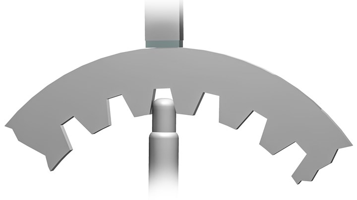
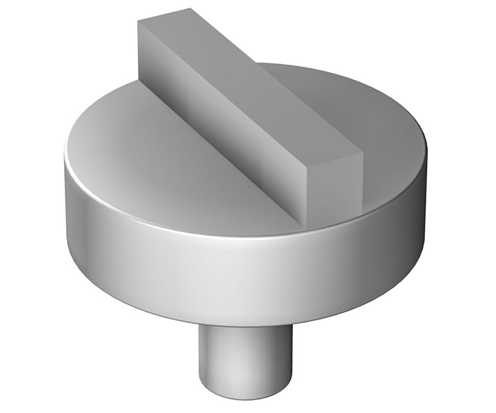
Tungsten carbide rods can be fixed to anvils for checking a diameter in a recess or for measuring pitch diameter of gears.


Related Content

4 Ways to Establish Machine Accuracy
Understanding all the things that contribute to a machine’s full potential accuracy will inform what to prioritize when fine-tuning the machine.
Read More
Ballbar Testing Benefits Low-Volume Manufacturing
Thanks to ballbar testing with a Renishaw QC20-W, the Autodesk Technology Centers now have more confidence in their machine tools.
Read More
Understanding Structured Light Scanning Measurements
Structured light scanning is used to create a digital twin of a manufactured part, but we must understand the measurement reproducibility to best use the data.
Read More
Orthopedic Event Discusses Manufacturing Strategies
At the seminar, representatives from multiple companies discussed strategies for making orthopedic devices accurately and efficiently.
Read More