
Toward A Truly Open Manufacturing Environment
Modular systemization is revolutionizing machine tool control. CNCs are only the beginning.
Share


Fig.6—CAD/CAM integration: linear interpolation vs. non-linear interpolation.
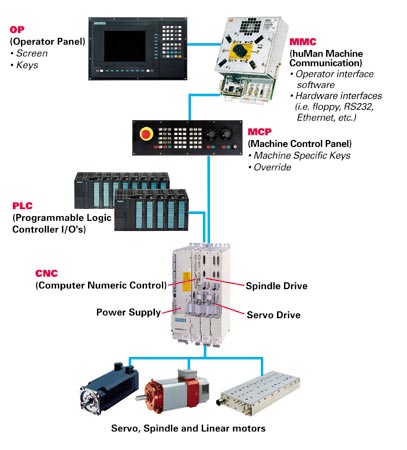
Fig.2—A common CNC system design.
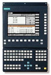
Fig.4—A control shown running shopfloor programming software.
Fig.7—Conventional interpolation vs. non-linear interpolation on a universal interpolator-based control, for a complex automotive part.

Fig.1—The NC kernel is the center of the open architecture CNC system.
Fig.5—CNC communications by Ethernet (TCP/IP).
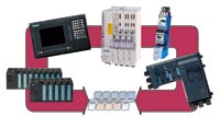
Fig.3—PROFIBUS greatly increases the machine tool builder's choice of I/O hardware and devices, while significantly decreasing machine wiring.
In the pursuit of ever increasing productivity, control systems for manufacturing processes have come under intense scrutiny. Developments realized in the last ten years are now setting the stage for the next 100 years. It’s likely that when technical historians look back at the 20 years spanning the second and third millennia, they’ll attribute a huge gain in output to the strategic implementation of integrated manufacturing and production technologies, coupled with the optimization of the human-machine interface.
Since their introduction, numerical control (NC) and later computer numerical control (CNC)-based systems have truly revolutionized metalworking by incorporating the latest advances in electronics, programming techniques and information technology. Control over the motion and myriad functions of a contemporary machine tool comes from a small set of core technologies. These technologies are centered around the motion control software in the CNC, which in turn serves as a real-time communication hub for the human-machine interface (HMI), programmable logic control (PLC), and motor and drive systems. (See Figure 1, below) Each of these systems plays a key role in the automation of a modern machine tool.


These core control technologies have matured over the past two decades, resulting in overall gains in usability, reliability, and—perhaps most importantly—the productivity of CNC machines. Generally, the major control suppliers have worked to harmonize control and motion while modularizing the various subsystems. (See Figure 2, see below) In the process, control suppliers have integrated new functionality into their products without sacrificing ease of operation or control scalability.
CNC Anatomy
The NC kernel is at the center of a CNC system. The NC kernel processes the NC part program and controls positioning of the machine axes. It also interfaces to the three main subsystems of the control—PLC, HMI and the drives. In some cases, these functions may be located on the same hardware processor, but as the demands on the machine tool increase, each function is delegated to an additional processor. CNC systems used for high performance machines typically have separate processors for the CNC and each of the subsystems. Frequently, additional processor hardware is added with each additional axis to ensure fast update times in the drive control loops.
While control system manufacturers offer complete solutions, the machine tool design of a given original equipment manufacturer (OEM) may require hardware or software components from a third-party supplier. The requirement might be something as simple as adding two or three additional machine-specific screens to the operator display or running a third-party spindle motor, or as complex as adding a new OEM-specific function into the NC kernel. The openness of the NC kernel, coupled with the control vendor’s ability to support an open system approach, has become a key CNC feature for machine tool builders seeking to differentiate their own machines from their competitors’.
PLC
The physical interface to machine I/O and the associated interface control function is delegated to the PLC, which is integrated into the CNC system. While digital I/O is sufficient for most machine tools, PLCs also offer the possibility for analog I/O and the use of function modules for specialized tasks. While programming of the PLC is by its very essence open to the machine builder, in recent years the incorporation of factory I/O networks such as PROFIBUS has dramatically increased the machine builder’s choice of I/O hardware and devices. For large machines, PROFIBUS significantly reduces the bulk of machine wiring, because the I/O modules can be remotely located near the controlled devices. As a nonproprietary standard, PROFIBUS provides the ultimate in openness by empowering the OEM to design a device to its own specifications. (See Figure 3, at right)
HMI—Man And Machine
A look at what’s state-of-the-art on the front end reveals a whole new approach to how machine tools of all types can now be integrated into a given manufacturer’s production setting. The typical HMI of ten or 20 years ago was limited in its openness because the HMI was incorporated into the CNC system software, which typically was written in assembler code that ran on customized proprietary hardware. Today’s level of openness has been realized due to the incorporation of separate, PC-based hardware platforms for the HMI, along with modular software techniques and nonproprietary development tools. By making open access to the HMI a design priority in the initial phases of CNC development, interfaces have been developed that provide the required access while at the same time protect the integrity of the motion control algorithms of the CNC itself.
Machine tool builders now have access to a wide range of tools to customize both the operating screens and the hardware platform for the HMI. As a result, today’s machine builders are limited only by their own vision and development budget as to the structure of the front end. While it is not the norm, it is not unheard of to have an HMI consisting of 100 percent OEM-generated operator screens running on an industrial PC and display. In this case, the only product actually sourced from a CNC supplier for the HMI is the communication protocol used to realize the CNC/HMI interface. Furthermore, by using standardized data handling protocols and adapting them to well-known operating systems like Windows, machine tool designers are offered not only access to the control’s internal components, but also access to components of the manufacturing process typically thought of as residing apart from the machine tool. (See Figure 4, at right)
Networking Via HMI
Such openness has special meaning for medium to large manufacturers, especially those companies that produce large quantities of complex machined parts. In such a capital-intensive environment, the benefits of securing the maximum utility from every machine are clear. How is it possible to make optimal use of all the machines? By connecting them to a factory communications network.
In practice, the installation of an Ethernet network communications card into an open HMI, along with the related software drivers, is one of the most typical applications. Intelligent networking improves NC program management and relegates punched tape, diskettes and other storage media to the dustbin of history. Intelligent networks, facilitated by integrating standardized software modules and Ethernet, offer manufacturers a consistent solution with a uniform data acquisition platform—one that transcends location or production sector, and can unite various CNC controls, programming workstations and tool-setting equipment. Across networks like these, the data transfer rate has been accelerated to the point where even very large programs, which used to take hours to transfer via serial interfaces, can now be transmitted to a machine in just seconds. (See Figure 5, below)
However, more effective CNC communication promises more than faster transfer of NC programs and production data within the factory network. For example, by incorporating a modem interface card and the corresponding software, remote access to the diagnostics of a CNC machine can be achieved. With remote diagnostics, a technician in a central location—such as the machine tool builder’s headquarters—can go online with the CNC to diagnose problems in real time, determine a corrective course of action, then send the appropriate commands to execute the fix. All of this can be accomplished without having the technician visit the site.
Drives And Motors
Drive and motor technology has also advanced. Modern digital drive systems offer faster processors—typically DSPs—and incorporate control algorithms that allow the control to be adapted to a given mechanical system. These recent drive technology enhancements have not only improved performance for machines based on traditional mechanical transmissions, they also have permitted a machine tool’s servo axes and spindles to be based on a variety of direct drive motor types. Direct drive motors can eliminate mechanical interfaces like gearboxes, pulleys and ballscrews, resulting in a faster, more dynamic machine that requires less overall maintenance.
While direct-drive induction motor spindles have existed for many years, recent advances in drive power electronics, feedback devices and control algorithms—coupled with improved mechanical elements—have dramatically increased spindle speed and power ratings. New control algorithms coupled with permanent magnet motors now make it possible for suppliers to create main spindle designs that can deliver higher torque for a given spindle volume, and they do so at lower bearing operating temperatures for extended life and reliability.
The application of direct drive linear motors permits speeds and accelerations not possible with traditional mechanical transmissions, but presents new design challenges to machine builders. Several builders have incorporated direct drive rotary—or torque—motors into rotary axes to replace traditional gearbox-based designs.
Drive performance is also critical for direct-drive servomotors. Although the elimination of mechanical components is a direct-drive system’s key advantage, the design can remove the mechanical stiffness that went along with these components. In part because direct-drive designs lack the inherent stability of ballscrew or gearbox preload, linear motor axes are highly dependent on the drive system to keep the axis in position and reject external disturbances.
The key to applying this technology effectively is to incorporate a common drive hardware and software platform for all motor types—rotary or linear, induction or permanent magnet—which allows the machine tool builder to select both the drive hardware and the motor type most appropriate for a particular machine. For applications demanding the highest level of performance, each axis can be configured with its own processor module to keep drive update times to a minimum. Thus, it is this kind of modularization and integration that is increasingly being used to reduce complexity and cost, while providing users with production equipment that is more productive and more reliable, and consequently less expensive to operate.
Open To Third Parties
Another area of system openness machine tool designers and users need to consider is the ability of a drive system to run a third party motor, or the CNC to interface to a third party drive. The vast majority of machines are built with motors and drives from the CNC vendor because the integration and after-sales support for a complete control system can be obtained simply and without confusion from the single-source supplier. In some cases, however, a given machine axis or spindle may require a unique motor not offered by the builder’s CNC/drive supplier. In this instance, the CNC/drive system must be open enough to operate the third party motor or to be interfaced to a third party drive, which in turn controls the third party motor. However, it is important to keep in mind that while this approach can solve a short-term problem, it can also create challenging startup issues (such as optimizing the special motor the first time) or set the stage for future support and troubleshooting problems with the machine.
New Paradigms For Motion Control
As mentioned, the CNC is at the heart of the machine’s motion control. Over the last ten years, CNCs have evolved from being proprietary and dedicated to specific types (CNCs for milling, turning, grinding and laser machines) toward more open and flexible platforms. For all concerned, this trend has huge implications. By taking advantage of the open platform and ongoing developments from the microprocessor industry, today’s modular CNC can be configured for a wide variety of machine types and performance levels—from simple two-axis turning centers to five-axis high speed machining centers to multistation transfer lines.
These breakthroughs, and other advances in control technology, have allowed machine tool designers to realize unprecedented gains in speed, flexibility, reliability and accuracy. Although faster processors, integrated digital drives and new machine designs have brought many benefits, competition and other commercial dynamics continue to create fiefdoms of systemization that create barriers to further integration. In order to take full advantage of the capabilities of a CNC, it is necessary to examine the complete machining process so that conflicts between the various manufacturing systems do not set up artificial limits to overall machine tool performance.
For example, the standard practice of generating NC part programs from computer-aided design (CAD) and computer-aided manufacturing (CAM) systems has produced certain incompatibilities. Historically, the CAM system has converted the CAD model (along with associated tooling and machining data) into a CNC program consisting of linear moves. This CAD/CAM/CNC interface was developed during a time when CNC was limited to straight lines and arcs of constant radius, and it has not been altered significantly in the past 30 years.
Traditional CNC systems have been optimized to process programs based on these linear blocks as fast as possible. One way to speed up machining is to realize faster point-to-point processing within the control. However, when machine tool users seek to machine parts with complex geometries, the number of linear blocks the control has to process can increase a great deal. For example, to improve a given part’s first pass surface finish, a user might tighten CAM tolerance—a strategy certain to increase the number of linear points to process. Providing enough processing power to accommodate the competing demands of processing speed and large-part-program management can add a great deal to the cost and complexity of the CNC system.
One technique to improve the overall machining process is to incorporate non-linear interpolation into the NC program. This is analogous to a mechanical draftsman choosing a “French curve” to draw a contoured surface rather than resorting to a series of lines drawn from point to point along the arc using a straight edge. By programming a required tool path based on curved segments instead of linear ones, the number of segments required to generate the overall tool path at the desired accuracy is dramatically decreased. Thus, processing this type of tool path is much more efficient and less demanding on processor capacity. Consequently, the programmed tool path feed rate can be dictated by considerations like machine stiffness, tooling, and workpiece materials, not the ability of the CNC to process thousands of linear blocks. (See Figure 6, at right)
Universal Interpolator
The trend in CNC has been to follow the lead of the CAD/CAM industry by going beyond the limitation of lines and arcs in the internal algorithms of the control. Traditional CNC uses different algorithms to process linear, circular and helical motion blocks. With this method, not all control features are programmed into every interpolation type, and the addition of a new interpolation type requires a major change in the software architecture. Some more modern CNCs are based on a “Universal Interpolator” in which all programmed interpolation types are converted within the CNC into a common mathematical representation. With this method, all CNC functions are available, independent of the programmed types.
CAD/CAM And NURBS
For some time now CAD/CAM system developers have relied on the Non-Uniform Rational B-Splines (NURBS) to represent the workpiece geometry. NURBS entities are used because of their ability to represent complex three-dimensional contours. But while the NURBS representation works for CAD models, it may not be the best choice for the real time motion control algorithms of a CNC. The representation of the tool path is limited to a third-order polynomial representation. However, a “universal interpolator” based on the third-order polynomial format can represent all traditional interpolation types (line = first-order polynomial, circle = second-order polynomial), as well as a variety of new interpolation formats that allow curved contours to be programmed efficiently.
A sharp contrast can be made between traditional CNC designs and those controls based on the Universal interpolator. Currently, several control suppliers using traditional CNC design can be programmed using “NURBS” interpolation, but these systems restrict CNC functionality when operating in NURBS mode. These restrictions include limiting programming to a maximum of three axes, not allowing changes to the programmed feed rate, not permitting active tool offsets, and not allowing a search to a block in the middle of the NURBS contour. By comparison, a universal interpolator-based CNC running the same program converts the programmed moves from the NURBS format into an internal polynomial representation that is processed with full CNC functionality thereafter.
Programming the CNC using an interpolation that represents curvature accurately can deliver dramatic results. In one test, a complex automotive part containing creases, indentations, sculptured surfaces, sharp edges and abrupt contour changes took 83 minutes to machine using a conventional control. The same part was machined in 33 minutes using a universal interpolator-based control, in spite of the control having to convert the point-to-point data in real time. (See Figure 7, at right)
Openness Beyond The HMI
True control openness means different things to different people. For a machine tool builder, the decision to go with one control technology over another is driven by many factors. They include the standard capabilities of the CNC system and the ability of the system to incorporate unique machine tool functionality. Many OEMs, especially those with unique machine features or those that have previously manufactured their own CNC system, demand open access into the core of the CNC that goes beyond the PLC or HMI. Another critical factor in the decision-making process is the ease with which OEM-specific functionality can be integrated into an off-the-shelf CNC platform, then applied to control the machine as the OEM designer(s) envision.
One way to accomplish this ease of integration is to incorporate cycles known as synchronous actions, which can be triggered by external events, or that can be based on the status of internal CNC variables such as spindle power or axis position. A second option is to allow builders direct access to the NC kernel so they can supplement the motion control algorithms to suit their needs. So, instead of having to develop and maintain complex, expensive proprietary controls to produce desired performance or functional characteristics, tool builders can now opt for controls that allow access to the NC kernel and permit synchronous actions. By specifying a standard, off-the-shelf hardware and software platform with these features, machine tool designers can cut the cost of controlling a particular machine effectively. In addition, they spread this cost efficiency to other machines, because a single CNC platform can be customized to fit the entire product line.
For example, a laser cutting tool manufacturer recently introduced a new plate cutting machine that takes particular advantage of the benefits that open architecture and component modularity can offer. The OEM started with standard catalog components including the CNC, I/O, drives, and rotary and linear servomotors based on his performance requirements. The OEM chose to develop its own HMI operator screens (which run on a third-party industrial PC), based on the unique requirements of its own laser programming software and the associated machine. Additionally, laser control algorithms developed by the OEM were incorporated directly into the NC kernel. The combination of standard control hardware and an open NC kernel helped to bring about a highly versatile machine with unprecedented ease of use, accuracy and flexibility.
Open Possibilities
For machine tool builders, users and other control specifiers, discovering what truly open controls can do is like taking blinders off. Suddenly, the whole horizon is visible and the old way of doing things is no longer the only way of doing things. Now, machine tool builders can build in unprecedented functionality, accuracy and productivity, and offer these benefits in a competitively-priced standard package.
For metalworking facilities, new machine tools offer more value than ever before. They also offer a chance to standardize controls and HMIs across the entire production setting—on all CNC machines regardless of age, axes or function. Cross-platform training becomes a thing of the past, and integrating new and old machines into a seamless, networked manufacturing matrix is no longer an exercise in patch, cut and fit.
It may not be that the machine age is being eclipsed by the electronic age. Instead, the ongoing integration of automation technologies into the industrial processes is creating a new age, the electronic machine age. Machine builders and their control suppliers are embracing the principles of system openness, and the change is now reaching machine tool users of all levels. MMS
About the author: Bernd Heuchemer is marketing manager for Siemens Energy & Automation.


.png;maxWidth=300;quality=90;format=webp)


Related Content

Five-Axis Machines Speed NASCAR Engine Production
Moving from an aging set of five-axis mills to more advanced machines enabled Hendrick Motorsports to dramatically improve its engine production.
Read More
The Smarter Way to Take Full Control of Your CNC Machine Shop
Designed to bridge the gap between CAM programmers and shop floor operators, SolidShop provides a seamless, real-time solution for managing G-code, tracking production and eliminating costly mistakes.
Read More
10 Robotic Solutions You Can Find at IMTS 2026
Discover how today’s robots and cobots are making it easier than ever to automate tasks, free up skilled workers, and run machines unattended – even in small and midsized shops.
Read More
Aerospace Shop Thrives with Five-Axis, AI and a New ERP
Within three years, MSP Manufacturing has grown from only having three-axis mills to being five-axis capable with cobots, AI-powered programming and an overhauled ERP. What kind of benefits do these capabilities bring? Find out in our coverage of MSP Manufacturing.
Read More