
When Little Things Mean A Lot
Measurement technology plays a role on machining centers used at high speeds.
Share


Fig. 2—While the spindle warms up to a new speed, the tool length offset varies along a curve that looks like this. Temperature sensors in the spindle can allow a CNC to compensate for this change, eliminating the need for a delay.
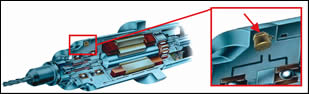
Fig. 3—An accelerometer near the front bearing continually monitors the severity of vibration.
Fig. 1—For a spindle capable of 42,000 rpm, this graph shows the change in Z-axis tool tip position resulting from centrifugal expansion of the bearing. This speed-dependent change is a repeatable and linear effect.

A laser tool setting device allows tool offsets to be measured while the tool is running at full speed. Photo courtesy of Blum LMT.
There are thresholds beyond which the little things begin to loom large. All of physics works that way, in fact; at a certain small size, Newton’s laws no longer make sense, and you need to rely on quantum mechanics instead. There comes a point, in other words, where assumptions have to change, because effects that were previously ignored must now be taken seriously.
Something like this critical threshold exists along the range of spindle speeds available on today’s metalcutting machining centers. At the slower, more conventional speeds, there are a number of sources of dimensional uncertainty that are likely to be too small to affect the process. Both the spindle and the process can be designed in standard ways.


But at higher speeds, thermal expansion, centrifugal expansion and unbalance all become significant enough to have an impact on the accuracy of almost any cut. Both the spindle and the process have to change. The threshold occurs around 20,000 rpm, says Mal Sudhakar, vice president for machine tool supplier Mikron (Lincoln, Illinois). Beyond this speed, the safe assumptions about spindle performance are not so safe anymore. The little things begin to mean a lot.
Mikron is one example of a company offering machining centers for die/mold and production milling work that go much faster than this threshold speed. The company has standard spindles with top speeds around 40,000 and 60,000 rpm. Mr. Sudhakar describes how the design of these high-speed machines, as well as process for using them, relies on measurement and sensor technology to take control of the effects that come into play at the highest values of rpm.
Centrifugal Expansion
Centrifugal force is a one of these effects. The higher the value of rpm, the more force is exerted to pull all of the spinning components outward from the axis of rotation.
Where machining accuracy is concerned, the effect of centrifugal force at the bearing is particularly important. High-rpm spindles generally use angular-contact bearings that constrain the spindle’s shaft in both the radial and axial directions. As centrifugal force becomes high enough that it begins to have a significant effect on the components of this bearing—as it pulls the rotating balls outward, for example—the way that the shaft seats in this bearing begins to change. Specifically, the shaft changes position in the axial direction. That means the tool tip position moves in Z.
It’s not the bearing’s fault that this happens. Centrifugal force is determined by the square of spindle speed. The difference between 10,000 and 20,000 rpm is a factor of two in terms of speed, but it brings about a four-fold increase in the force that the bearing sees. Similarly, increasing the speed from 10,000 to 40,000 rpm increases the centrifugal force by 16 times.
How much change in Z location does this force bring about? On a rigid machine, it should not be enough to impair any roughing cuts, but finishing is another matter. For its own 40,000 rpm spindle, Mikron has determined that the difference in tool tip position between 0 rpm and top speed is about 0.002 inch (see Figure 1). For a finish milling pass, that is certainly enough dimensional variation to be concerned about.
The best technology for compensating for this effect, Mr. Sudhakar says, is a non-contact toolsetting device such as the laser unit shown in the photo at the beginning of this article. (This particular unit is supplied by Blum Laser Measuring Technology) Mikron supplies this device as standard equipment on all of its high speed machining centers. Unlike the tool measurement devices that rely on touching the tool, this device can determine a tool’s measurements while the tool is spinning at its intended speed for cutting. That means the tool tip dimensions measured in this way will include the centrifugal effects.
Does that mean the tool has to be re-measured each time the spindle speed changes? Because the laser measurement takes about 30 seconds, such frequent measurement may not be acceptable for some applications.
Mr. Sudhakar says the answer is no. One characteristic of the Z-axis change resulting from centrifugal force is that it varies according to a repeatable, linear relationship. That means the CNC can predict changes. It does this using an algorithm the machine tool builder developed.
Knowing the tool tip measurement at one speed allows the CNC to predict what the measurement will be at any other speed. There is an uncertainty band for this prediction, as Figure 1 shows. Using the laser tool setter at the actual speed of cutting is likely to give a more accurate value. However, allowing the CNC to make a prediction in this way is another, faster solution that may also be acceptable.
Thermal Expansion
An unrelated factor that also changes the position of the tool tip is thermal expansion. Immediately after the spindle begins to run, or after it makes a dramatic increase in speed, there comes a period during which the spindle is heating up toward some steady-state distribution of temperatures associated with the new rpm value. The spindle’s dimensions are changing all the while that this temperature change occurs. That means a process for precision milling may need to include a “warm up” time before the tool offsets can be accurately determined. For an extreme change in speed combined with precise milling work, the wait time to reach the steady-state temperatures might be 15 to 25 minutes.
But here is another case where measurement technology combined with algorithms in the CNC can reduce the amount of lost time. In the case of thermal expansion, the algorithms draw on data captured from temperature sensors throughout the spindle. The thermal expansion, like the centrifugal expansion, is a repeatable effect; however, it is not a linear effect. Modeling the thermal behaviors of a particular spindle design accelerating to a particular speed yields a curve shaped like the one in Figure 2. As an alternative to waiting for the spindle to warm up, says Mr. Sudhakar, the CNC can allow for thermal expansion during the warm-up period by continually adjusting the tool offset in accordance with such a curve. The CNC can control the accuracy of the cut to within 20 microns in this way, without allowing for any warm-up delay.
The CNC can hold an even tighter accuracy (10 microns) if the machine is allowed to retain just 3 minutes of the warm-up delay. Why the difference for this short wait? Because there are components of the process for which no temperature readings are available. Consider the toolholder, for example. In most cases, a tool change will consist of inserting a “cold” toolholder into a “hot” spindle. The size of this toolholder therefore will change much faster than the size of the spindle, as the toolholder’s temperature races to catch up. A small wait time can allow the heat and thermal expansion of the tooling to settle into parity with the expansion of the rest of the system.
Vibration
One more effect that becomes pronounced at higher values of rpm is vibration. It may be a product of the interaction between the tool and workpiece that produces chatter, or it may come from centrifugal force acting on some unbalanced mass in the tool-toolholder assembly. The first of these effects tends to become more pronounced as speed increases, while the second of these effects can only become more pronounced as speed increases, because of the relationship between centrifugal force and speed. In either case, controlling vibration is essential not only to the accuracy and productivity of the process, but also to the lives of the spindle and the tool.
Mikron’s system for controlling vibration involves accelerometer readings of the spindle’s front bearing (see Figure 3). These measurements provide the data for a system the company refers to as its “Advance Process System,” or APS. The system recognizes that the ear of the operator or machinist is no longer an appropriate means of managing vibration when a 40,000-rpm machining center is involved.
For processes attended by an operator, APS presents a multicolor display on the CNC interface. The color of the vibration reading—green, yellow or red—gives the operator an immediately recognizable clue as to the severity of vibration the machine is seeing. Vibrations below 3G (three times gravity) fall in the “green” range, vibrations below 6G are “yellow” and anything beyond that is red.
Diagnostic work is still necessary to find the source of the problem, but these readings make it possible to narrow down the potential culprits. Vibration severity that changes as the depth of cut changes is more likely to involve chatter, while vibration that continues both inside and outside the cut is likely to be the result of an unbalanced weight.
Mr. Sudhakar says this control feature can also play a role in unattended machining. For example, the control might be programmed to stop the process if a certain level of vibration is detected. Alternately, the CNC could track the vibration continuously, generating a collection of data at the end of the cycle that matches each vibration reading to a particular block of NC code. Using these data, a shop can determine whether there are particular cuts or particular part features that are routinely causing chatter, and then adjust the machining program accordingly.


.png;maxWidth=300;quality=90;format=webp)


Related Content

Five-Axis Machines Speed NASCAR Engine Production
Moving from an aging set of five-axis mills to more advanced machines enabled Hendrick Motorsports to dramatically improve its engine production.
Read More
The Benefits of In-House Toolmaking
The addition of two larger gantry routers has enabled a maker of rubber belting products to produce more tooling in-house, reducing lead times and costs for itself and its sister facilities.
Read More
The Power of Practical Demonstrations and Projects
Practical work has served Bridgerland Technical College both in preparing its current students for manufacturing jobs and in appealing to new generations of potential machinists.
Read More
How to Build Out a Machine Shop for Submarine Parts
Five-axis large-format machining has given Granite State Manufacturing the ability to take on complex submarine parts — and has also worked as a recruiting tool for experienced machinists.
Read More